Method for charging electrically operated vehicle at standstill

A technology for a vehicle and a charging station is applied in the field of devices implementing the method to achieve the effect of shortening the charging time

Active Publication Date: 2019-08-16
VOLKSWAGEN AG
View PDF13 Cites 0 Cited by
  • Summary
  • Abstract
  • Description
  • Claims
  • Application Information

AI Technical Summary

Problems solved by technology

This type of charging comes with the disadvantage that the driver of the vehicle has to get out of the vehicle and do it himself in order to make the electrical connection

Method used


Image

  • Method for charging electrically operated vehicle at standstill
  • Method for charging electrically operated vehicle at standstill
  • Method for charging electrically operated vehicle at standstill

Examples


Embodiment Construction

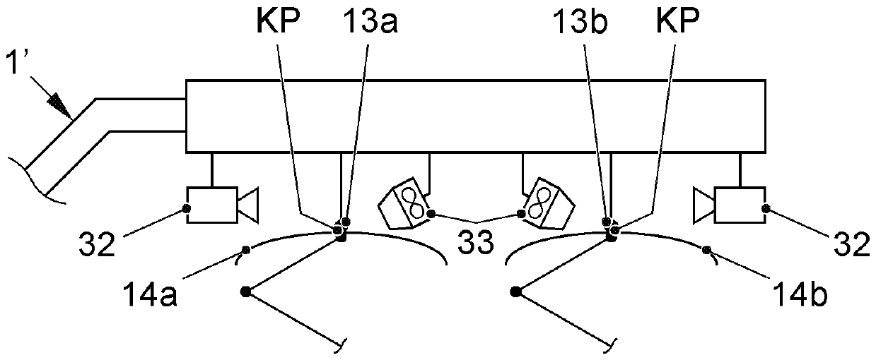
[0087] exist figure 1 A charging station 1 for an electrically operable vehicle K is shown in . In this exemplary embodiment, the vehicle K is an electrically runable truck. As can be seen, the charging station 1 has a stand body 10 fixed to the ground 3 . Extending upwards from the stand 10 is a utility pole-like support 11 which carries a movement device 12 for moving an electrical conductor 13a (positive pole) and an electrical conductor 13b (negative pole).

[0088] The movement device has an upper part 12a and a lower part 12b held movably, preferably displaceably, relative to the upper part.

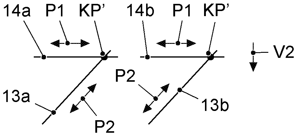
[0089] The movement device 12 , not shown in more detail in terms of its kinematics, allows the movement of the lower part 12 b in the direction of the drawing plane in a horizontal path of travel V1 and in a horizontal path of travel V2 perpendicular thereto.

[0090] The station body 10 is also used to accommodate a voltage source 16 , which supplies the conductors 13 a and 13...


PUM


Abstract

The invention relates to a method for charging an electrically operable vehicle (K) while the vehicle is parked. In the method, at least one current collector (14a, 14b) on the roof side of the vehicle (K) is brought into contact with at least one conductor (13a, 13b) of the charging station (1), said conductor being arranged above the vehicle (K). Several possibilities are proposed in order to avoid overheating of the contact area during charging and thus to achieve a high transfer power. It is therefore proposed to move the conductors (13a, 13b) in order to form locally varying contact points between the conductors (13a, 13b) and the current collectors (14a, 14b). It is alternatively proposed to cool the contact points present between the conductor and the current collector or to form linear contact regions between the conductor and the current collector.

Description

technical field [0001] The invention relates to a method for charging an electrically operable vehicle and a device for carrying out the method. Background technique [0002] It is known from the general prior art to charge electrically operable vehicles by means of a connection of a charging plug to a charging socket on the vehicle side. This type of charging entails the disadvantage that the driver of the vehicle has to get out of the vehicle and do it himself in order to make the electrical connection. [0003] It is also known to charge or operate electrically operable vehicles by means of overhead lines. [0004] A device is known from DE 203 14 496 U1 for raising and lowering again a section of a trolley chain, wherein the section is located between two adjacent utility poles. In particular, at each of the utility poles there is a vertical guide bar for a slider to which a boom holding the overhead wire chain suspension is connected. The slider is in turn connected ...

Claims


Application Information

Patent Timeline
Patent Type & Authority Applications(China)
IPC IPC(8): B60M1/36
CPCB60M1/36B60L53/14B60L53/32B60L53/11B60L53/302Y02T10/70Y02T10/7072Y02T90/12
Inventor A.韦斯H.S.福格特
Owner VOLKSWAGEN AG
Why Eureka
Try Eureka