Conic sand making machine comprising concave-convex arc-shaped sand making cavities and sand making method

A conical sand making machine, concave arc technology, applied in the direction of grain processing, etc., can solve the problems of sand grinding bridge, increase, spindle fracture, etc.

Active Publication Date: 2015-05-06
ZHEJIANG SHUANGJIN MACHINERY HLDG
View PDF9 Cites 0 Cited by
  • Summary
  • Abstract
  • Description
  • Claims
  • Application Information

AI Technical Summary

Problems solved by technology

Since the mortar surface of the mortar wall in the sand-making chamber is in linear contact with the crushing surface of the crushing wall, in actual use, the huge force generated by the sand-making chamber in order to crush stones during sand-making is useless. Dispersion, directly acting on the main shaft, causing frequent breakage of the main shaft; secondly, because the sand making chamber is crushed by surface extrusion, when the water content of the stone is slightly larger, it will cause sand grinding and bridging, resulting in no sand in the sand making chamber suffocation, the motor current increases sharply, causing the motor to be burned due to excessive current, and the wall of the mortar and the broken wall are damaged.

Method used


Image

  • Conic sand making machine comprising concave-convex arc-shaped sand making cavities and sand making method
  • Conic sand making machine comprising concave-convex arc-shaped sand making cavities and sand making method
  • Conic sand making machine comprising concave-convex arc-shaped sand making cavities and sand making method

Examples


Embodiment 1

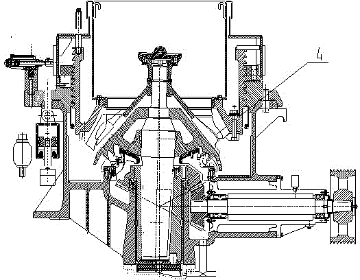
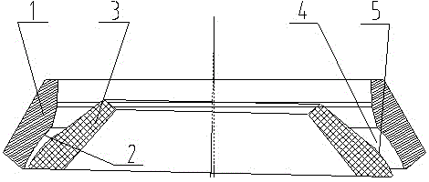
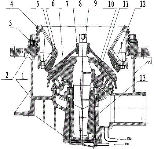
[0011] Embodiment 1: with reference to attached figure 1 and 2 . A conical sand making machine composed of a concave-convex arc-shaped sand making chamber, including a conical sand making machine, the mortar surface 2 of the mortar wall 1 in the sand making chamber 4 of the cone sand making machine and the crushing surface 5 of the crushing wall 3 It is a concave-convex arc-shaped surface, and the mortar wall 1 and the crushing wall 3 are made of high-chromium cast iron, which are cast and formed by high-chromium cast iron and then finished.

Embodiment 2

[0012] Embodiment 2: On the basis of Embodiment 1, the piercing surface 2 of the piercing socket wall 1 is concave arc-shaped, and the crushing surface 5 of the crushing wall 3 is convex arc-shaped. The radius of the concave arc-shaped grinding surface 2 is 308-328 mm, and the radius of the convex arc-shaped crushing surface 5 is R180-200 mm. The technical effect produced not only improves the efficiency of sand grinding, but also well disperses The grinding force is concentrated on the main shaft to reduce and transfer the sand grinding force, which reduces the energy consumption required for sand grinding. At the same time, the amount of sand produced by sand grinding is large, which avoids the phenomenon of sand bridging.

Embodiment 2-1

[0013] Example 2-1: On the basis of Examples 1 and 2, the radius of the concave arc-shaped piercing surface 2 is 308 mm, and the radius of the convex arc-shaped crushing surface 5 is R180 mm.


PUM

PropertyMeasurementUnit
radiusaaaaaaaaaa
radiusaaaaaaaaaa

Abstract

The invention relates to a conic sand making machine comprising concave-convex arc-shaped sand making cavities and a sand making method, so as to fundamentally solve the problems that the spindle of the conventional conic sand making machine is concentratedly stressed and easy to break, and sand made through sand bridging of the sand making cavities cannot fall off. Each sand making cavity of the conic sand making machine provided by the invention comprises a rolled mortar surface of a rolled mortar wall and a crushing surface of a crushing wall in the conic sand making machine, so that when small stone enters the sand making cavity under the action of the spindle of the conic sand making machine, the spindle drives the crushing surface of the crushing wall sleeved on a movable taper through the movable taper to move along an arc-shaped curve, so as to form curve rolling with the rolled mortar surface of the rolled mortar wall; and as the rolled mortar surface of the rolled mortar wall is in concave-convex arc-shaped linear surface fit with the crushing surface of the crushing wall, the arc-shaped curved surfaces rolled by the rolled mortar surface are different in angle with the rotation of the spindle, and the stressed positions of the arc-shaped curved surface of the rolled mortar surface of the rolled mortar wall are different. Therefore, the purpose of arc-shaped curve sand making without sand bridging is realized.

Description

technical field [0001] The invention relates to a kind of conical sand making machine and sand making machine composed of concave and convex arc sand making chambers which can fundamentally change the concentrated force and easy breakage of the main shaft of the conical sand making machine. The method belongs to the field of sand cavity manufacturing of a cone sand making mechanism. Background technique [0002] CN201552020U, name "a special sand making chamber for a conical sand making machine", the upper casing is located at the upper end of the lower casing, the adjusting screw sleeve is located on the upper casing and is spirally connected with the upper casing, and the inner wall of the adjusting screw sleeve is The middle is raised, and the upper and lower sides are respectively ring-shaped horn-shaped slopes. The anti-wear fixed sleeve is connected with the lower ring-shaped horn-shaped slope of the adjusting screw sleeve through the fixed sleeve bushing. In the shaf...

Claims


Application Information

Patent Timeline
Patent Type & Authority Patents(China)
IPC IPC(8): B02C2/00
Inventor 胡祖尧
Owner ZHEJIANG SHUANGJIN MACHINERY HLDG
Why Eureka
Try Eureka