Processing molds for sheet metal pipe clamps

A technology for processing molds and metal sheets, which is applied in the field of processing molds for sheet metal pipe clamps, can solve the problems of elongation, warping and deformation of parts, and time-consuming and labor-intensive manual demoulding, so as to achieve accurate guiding and positioning, reduce bending force, and reduce friction Effect

Active Publication Date: 2015-10-21
AVIC HUIYANG AVIATION PROPELLER
View PDF5 Cites 0 Cited by
  • Summary
  • Abstract
  • Description
  • Claims
  • Application Information

AI Technical Summary

Problems solved by technology

[0002] At present, the mechanical processing of sheet metal pipe clamp parts is difficult to rely solely on the operator to bend and form at one time, and it needs repeated corrections, poor interchangeability, long time-consuming, basically unable to meet the requirements of design drawings, and low production efficiency
Using existing molds to process sheet metal pipe clamp parts, the process used is blanking, bending forming, repairing and drilling; the processed pipe clamps are all right angles and straight edges, which require manual bending and deformation, especially The transition angle of the pipe clamp is arc-shaped, and it is very difficult to reprocess manually; the upper part of the upper die is cylindrical, and the force exerted on the blank is uniform, because the position of the bending line at the outer corner of the arc-shaped transition angle changes during the bending process Yes, the material is elongated when bent, the shape of the outer corner is inaccurate, the vertical edge becomes thinner, and the whole processed part is prone to warping and deformation. The mold is only suitable for occasions where the bending height of the part is not too high; and this The lower mold of this type of mold is an integral structure mold, and the processed parts cannot be automatically demolded, and manual demoulding is time-consuming and laborious, especially for cap-shaped parts, which require complex demoulding tools to assist demoulding

Method used


Image

  • Processing molds for sheet metal pipe clamps
  • Processing molds for sheet metal pipe clamps
  • Processing molds for sheet metal pipe clamps

Examples


Embodiment Construction

[0013] The present invention will be further described below in conjunction with the accompanying drawings and specific embodiments.

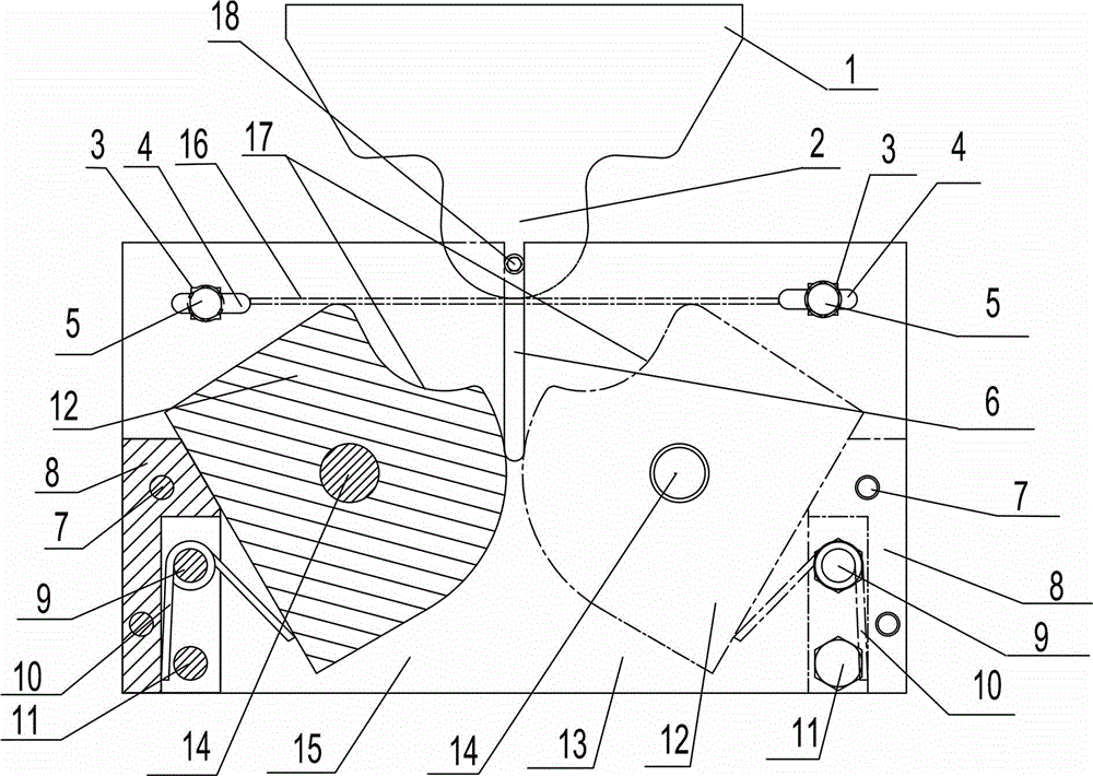
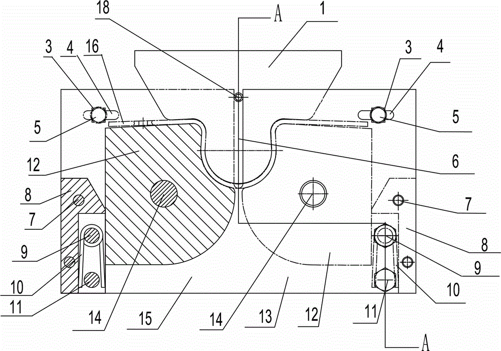
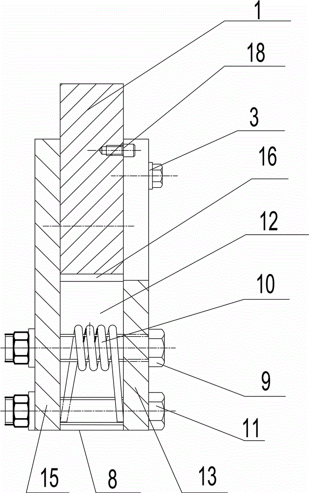
[0014] Such as figure 1 , figure 2 , image 3 and Figure 4 As shown, this embodiment includes an upper mold 1, a lower mold, a support positioning seat, a blank fixing assembly and a rebound limiting assembly. The upper die 1 is a convex die whose upper part is in the shape of an inverted cone, and the protruding part 2 of the lower part is the same as the internal shape of the processed part concave part. The lower mold is made up of the same shape, two recessed parts 17 after splicing symmetrically distributed and the same half-die 12 with the same external shape of the processed part concave part. The thickness of the upper mold 1 and the thickness of the lower mold are not less than the thickness of the blank. After the two are combined, the gap between them is the shape of the processed part. The support positioning seat is made up ...


PUM


Abstract

The invention discloses a mould for processing a sheet metal pipe clamp. An upper die is a male die with the upper part being inverted cone-shaped, and the projected part at the lower part of the upper die has the same shape with the interior part of the concave part of a finished part; a lower die consists of two symmetrically arranged half female dies with the same shape, and after the two half female dies are spliced together, the concave part of the spliced female dies has the same shape with the exterior part of the concave part of the finished part; the two half female dies are arranged in symmetry and can be clamped at the left and right ends of front and back support and positioning plates in a rotary manner; rebound limit assemblies of the two half female dies are respectively fixed between the front and back support and positioning plates which are located at the left lower corner and the right lower corner of the mould; a guide slot for the upper die is arranged at the middle position of the front or back support and positioning plate; a guide pin is fixed at the lower end of the upper die; and blank fixing assemblies are fixed above the front and back support and positioning plates. With the mould, the part under processing can be formed through single time of bending with high precision; the mould is free of the height limit of the part and can be demoulded automatically; the press tonnage requirement of the mould is lower; and no damage is caused to the structure of the material under processing.

Description

technical field [0001] The invention relates to a mechanical processing equipment, in particular to a metal plate pipe clip processing mold for fixing metal pipe fittings. Background technique [0002] At present, the mechanical processing of sheet metal pipe clamp parts is difficult to rely solely on one-time bending by the operator, and requires repeated shape correction, poor interchangeability, long time-consuming, basically unable to meet the requirements of design drawings, and low production efficiency. Using existing molds to process sheet metal pipe clamp parts, the process used is blanking, bending forming, repairing and drilling; the processed pipe clamps are all right angles and straight edges, which require manual bending and deformation, especially The transition angle of the pipe clamp is arc-shaped, and it is very difficult to reprocess manually; the upper part of the upper die is cylindrical, and the force exerted on the blank is uniform, because the positio...

Claims


Application Information

Patent Timeline
Patent Type & Authority Patents(China)
IPC IPC(8): B21D37/10B21D43/00
Inventor 崔小雨赵会捷赵春玲宋丽丽
Owner AVIC HUIYANG AVIATION PROPELLER
Why Eureka
Try Eureka