Edge cutting machine

An edge trimmer and edge trimming technology are applied in the direction of shearing devices, attachments of shearing machines, knives used in shearing machines, etc., which can solve the problems of not seeing edge trimmers, etc., and achieve the effect of reducing production costs

Inactive Publication Date: 2013-04-03
JIANGSU SANHUAN IND HLDG CO LTD
View PDF5 Cites 13 Cited by
  • Summary
  • Abstract
  • Description
  • Claims
  • Application Information

AI Technical Summary

Problems solved by technology

At present, there is no trimming machine for trimming soft metals such as lead strips on the market.

Method used


Image

  • Edge cutting machine
  • Edge cutting machine
  • Edge cutting machine

Examples


Embodiment Construction

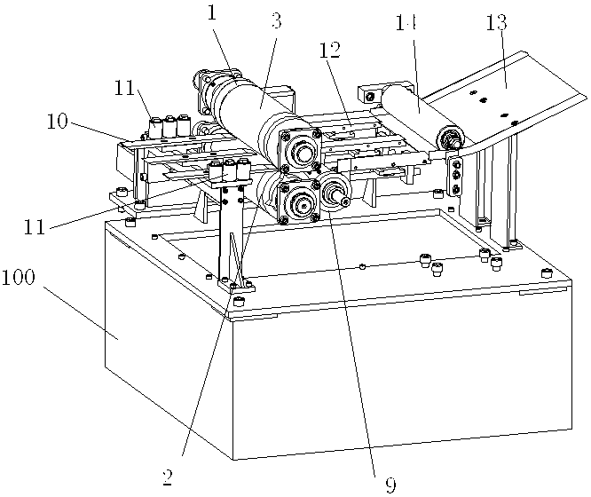
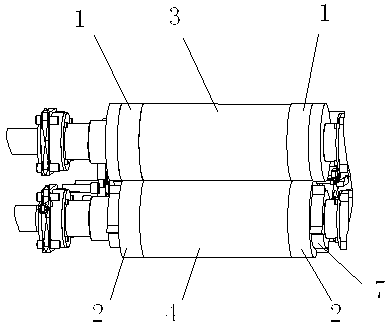
[0028] Such as Figure 1-4 As shown, the edge trimmer in the present invention includes a frame 100 and an edge trimming device, a shredding device, an introduction mechanism and an output mechanism arranged on the frame 100 . The trimming device comprises two upper cutters 1, two lower cutters 2, an upper drum 3, a lower drum 4 and a drum driving device composed of a motor 5 and a reducer 6. The upper drum 3 and the lower drum 4 are respectively arranged on the frame 100 through bearings at both ends. The axes of the upper roller 3 and the lower roller 4 are arranged parallel to each other, and preferably, they are located on the same vertical plane. There is a set gap between the adjacent roll surfaces of the upper drum 3 and the lower drum 4 in the vertical direction, and the gap should be determined according to the thickness of the lead tape to be cut. In general, the gap should be equal to or slightly larger than that of the lead tape. thickness. Both the upper drum 3...


PUM


Abstract

The invention relates to an edge cutting machine which comprises a frame and an edge cutting device, wherein the edge cutting device is arranged on the frame and used for cutting the edge of a lead belt; and the edge cutting device comprises an upper roller, a lower roller, a driving device, two upper cutters and two lower cutters, wherein the upper roller and the lower roller are matched and used for clamping and positioning the lead belt during edge cutting, the driving device is used for driving the upper roller and the lower roller to relatively rotate, the two upper cutters are respectively arranged on both ends of the upper roller and synchronously rotated along with the upper roller, and the two lower cutters are respectively arranged on both ends of the lower roller and synchronously rotated along with the lower roller. During edge cutting, the upper roller and the lower roller are driven to rotate by the driving device, so as to grip the lead belt, and the upper cutters which are arranged on the both ends of the upper roller and the lower cutters which are arranged on the both ends of the lower roller are used for cutting the edge of the lead belt in the process of rotation, wherein the edge is positioned between the upper cutters and the lower cutters. According to the edge cutting machine disclosed by the invention, the rotated upper cutters and the rotated lower cutters are manually matched to conveniently and quickly cut off the edge of the lead belt, edge cutting is performed during travel of the lead belt, and normal travel of the lead belt are not influenced, so that normal production of upstream equipment cannot be influenced by edge cutting.

Description

technical field [0001] The invention relates to an edge trimmer for trimming irregular edges for lead strips. Background technique [0002] Existing lead strip production is usually after lead strip is rolled to predetermined thickness, and lead strip is wound into lead roll and leaves the factory. Although in the rolling process, parameters such as the reduction rate of each pass are adjusted to ensure the flatness of the lead strip. However, due to the existence of uncontrollable factors, the edge of the rolled lead strip usually has defects such as wrinkles. In order to ensure the quality of the finished lead strip, it is necessary to trim the lead strip after the rolling process is completed. At present, there is no trimming machine for trimming the softer metal of the lead band on the market. Contents of the invention [0003] Aiming at the problems existing in the prior art, the purpose of the present invention is to provide an edge trimmer, which is arranged behin...

Claims


Application Information

Patent Timeline
Patent Type & Authority Applications(China)
IPC IPC(8): B23D31/04B23D19/06B23D35/00B23D33/02
Inventor 汪群华卢曦吴昊
Owner JIANGSU SANHUAN IND HLDG CO LTD
Why Eureka
Try Eureka