Wind drum left and right piece moulding plastic mould for electric room heater

A technology for forming plastic molds and electric heaters, applied in the field of plastic molding molds, can solve problems such as restricting the development of the plastic industry, increasing production costs, and increasing hardware costs, saving human and material resources, improving yield, and improving production efficiency. Effect

Inactive Publication Date: 2013-04-03
苏州市吴中区木渎华利模具加工店
View PDF4 Cites 2 Cited by
  • Summary
  • Abstract
  • Description
  • Claims
  • Application Information

AI Technical Summary

Problems solved by technology

However, based on the existing mold technology, in order to improve production efficiency, it can only be realized by adding injection molding machines and mold equipment, which will not only increase the hardware cost, but also the corresponding equipment maintenance costs and the consumption of electric energy, water energy and other operating costs. And labor costs are not a small expense. Therefore, the huge increase in production costs has seriously limited the development of the plastics industry.
[0003] The volume of the air drum left and right pieces of the electric heater on the existing market requires the plastic part to have high dimensional accuracy and molding interface. The existing plastic mold has low molding efficiency and low yield, which greatly increases the production cost. a waste of resource

Method used


Image

  • Wind drum left and right piece moulding plastic mould for electric room heater
  • Wind drum left and right piece moulding plastic mould for electric room heater
  • Wind drum left and right piece moulding plastic mould for electric room heater

Examples


Embodiment Construction

[0011] The preferred embodiments of the present invention will be described in detail below in conjunction with the accompanying drawings, so that the advantages and features of the invention can be more easily understood by those skilled in the art, so as to define the protection scope of the present invention more clearly.

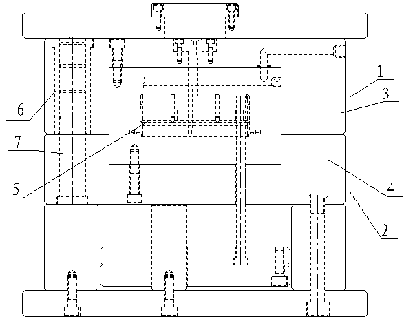
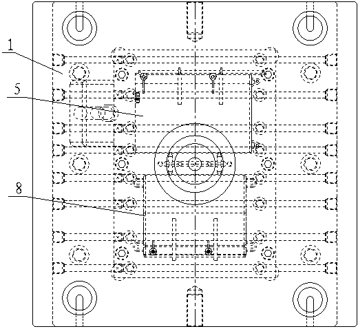
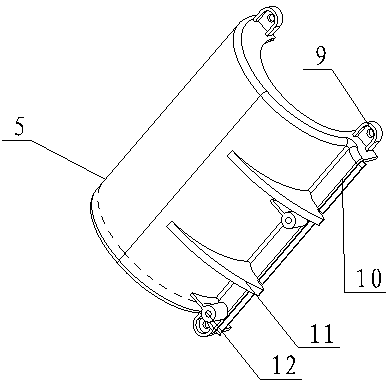
[0012] see Figure 1 to Figure 4 , the embodiment of the present invention includes:

[0013] A plastic mold for forming the left and right air drums of an electric heater, the plastic mold for forming the left and right air drums of the electric heater includes a fixed mold 1 and a movable mold 2, and a guide sleeve 6 is installed on the fixed template 3 of the fixed mold 1 , the guide sleeve 6 is inserted with a movable guide post 7, the guide post 7 is fixed on the movable template 4 of the movable mold 2, and the movable mold 2 performs opening and closing movement through the guide pillar 7; the movable mold 2 corresponds to the fixed mold 1 After ...


PUM


Abstract

The invention discloses a wind drum left and right piece moulding plastic mould for an electric room heater. The wind drum left and right piece moulding plastic mould for the electric room heater comprises a fixed die, a movable die, a feeding hole and a cooling water runner, wherein a fixed die plate of the fixed die is provided with a guide sleeve, a movable guide pillar is inserted into the guide sleeve, the guide pillar is fixed on a movable die plate of the movable die, the movable die does open and close movement by virtue of the guide pillar; the movable die and the fixed die are correspondingly occluded to form a wind drum left piece moulding cavity and a wind drum right piece moulding cavity, and the wind drum left piece moulding cavity and the wind drum right piece moulding cavity are symmetrically arranged along a lateral axis of the movable die plate; and the wind drum left piece moulding cavity is a semicircle cambered surface cavity three corners of which are respectively provided with screw connecting hitching leg cavities parallel to an axial section of an arc, and one straight edge of the wind drum left piece moulding cavity is provided with a splicing vertical side cavity. By adopting the manner, a production process can be simplified and more human and material resources can be saved, so that the wind drum left and right piece moulding plastic mould disclosed by the invention is applicable to flow line production of a product, production cost is saved, and production efficiency of an enterprise is greatly improved.

Description

technical field [0001] The invention relates to a plastic forming mold, in particular to a plastic mold for forming the left and right pieces of an electric heater. Background technique [0002] In recent years, with the rapid development and general use of the plastics industry, the strength and precision of engineering plastics have been continuously improved, making the application range of plastic products also expanding, such as household appliances, instruments and meters, construction equipment, automobile industry, Japan, etc. In many fields such as hardware, the proportion of plastic products is increasing rapidly. With the increasing demand for plastic products, higher requirements are placed on the output of plastic molds. However, in terms of existing mold technology, in order to improve production efficiency, it can only be achieved by adding injection molding machines and mold equipment, which will not only increase hardware costs, but also the corresponding e...

Claims


Application Information

Patent Timeline
Patent Type & Authority Applications(China)
IPC IPC(8): B29C45/26B29C33/30B29C45/32
Inventor 鲍常莲
Owner 苏州市吴中区木渎华利模具加工店
Why Eureka
Try Eureka