I-shaped wheel with flange side reference position measurement tool

A reference position and I-shaped wheel technology, applied in the field of cutting metal wires, can solve the problems of non-parallel flanges and affecting the quality of wire arrangement, etc., and achieve the effects of avoiding line arrangement errors, simple structure, and convenient operation

Active Publication Date: 2015-05-13
ZHENJIANG NAISI ADVANCE MATERIALS
View PDF5 Cites 0 Cited by
  • Summary
  • Abstract
  • Description
  • Claims
  • Application Information

AI Technical Summary

Problems solved by technology

But in actual production, the wire passing wheel is movable. When the wire passing wheel moves, it is easy to cause the metal wire to enter the I-shaped wheel and not parallel to the flange of the I-shaped wheel, thus affecting the arrangement of the metal wire on the I-shaped wheel. line quality

Method used


Image

  • I-shaped wheel with flange side reference position measurement tool
  • I-shaped wheel with flange side reference position measurement tool

Examples


Embodiment Construction

[0011] Below in conjunction with accompanying drawing and specific embodiment, further illustrate the present invention, should be understood that these embodiments are only for illustrating the present invention and are not intended to limit the scope of the present invention, after having read the present invention, those skilled in the art will understand various aspects of the present invention Modifications in equivalent forms all fall within the scope defined by the appended claims of this application.

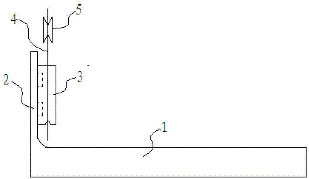
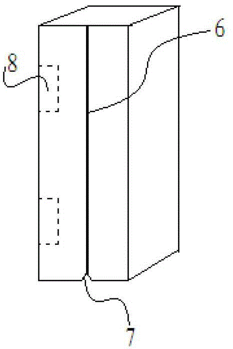
[0012] The invention is a tool for measuring the reference position of the flange side of the I-shaped wheel (the position where the steel wire is accurately reversed). The device can accurately measure the reference position of the flange, set the precise position of the reversing wheel, remove the tool, and then wind the wire on the I-shaped wheel, thereby improving the quality of the wire arrangement.

[0013] Such as Figure 1~2 As shown, a kind of I-shaped wheel wi...


PUM


Abstract

The invention discloses an I-shaped wheel with a flange side reference position measurement tool, which comprises a shaft tube, two flanges and a reference ruler, wherein the two flanges are vertically fixed at two ends of the shaft tube respectively; the reference ruler is fixed on the flanges, and a reference line parallel with the flanges is carved on the flange; a groove is formed at the lower end of the reference ruler corresponding to the reference line to serve as a reference point. Through adopting the I-shaped wheel, wire arranging error due to deformation or excursion of a wire wheel can be effectively avoided during winding the steel wires, so that the wire arranging quality is improved; and moreover, the I-shaped wheel is simple in structure and convenient to operate.

Description

technical field [0001] The invention belongs to the technical field of cutting wires, in particular to an I-shaped wheel for cutting metal windings. Background technique [0002] In the division and slicing process of hard materials such as monocrystalline silicon, polycrystalline silicon, and gemstones in the field of electronics and solar energy, the most used method is to use linear metal monofilaments to move in one direction or reciprocating under a certain tension. way to split slices. When the metal monofilament is moving, through the mortar transportation and injection system, before the metal monofilament contacts with the silicon rod and other objects to be cut, the mortar containing extremely hard abrasive particles is sprayed on the metal monofilament, and the metal monofilament is brought into the cutting process. Through the continuous grinding process of extremely high hardness abrasive particles and silicon rods, gemstones and other objects to be cut, the cu...

Claims


Application Information

Patent Timeline
Patent Type & Authority Patents(China)
IPC IPC(8): B65H75/18
Inventor 费鸿杰承建冬
Owner ZHENJIANG NAISI ADVANCE MATERIALS
Why Eureka
Try Eureka