Photovoltaic bracket for double-T plate plant roof

A technology for photovoltaic supports and workshops, which is applied to the support structure of photovoltaic modules, roofs, and roofs using tiles/slate tiles, etc., which can solve the problem of restricting the design and installation of photovoltaic support structures, weak wind load overturning force, and failure to report To reduce the risk of load-bearing, strong overturning resistance under wind load, and save materials

Active Publication Date: 2013-04-03
SUZHOU TALESUN SOLAR TECH CO LTD
View PDF0 Cites 1 Cited by
  • Summary
  • Abstract
  • Description
  • Claims
  • Application Information

AI Technical Summary

Problems solved by technology

[0002] Affected by the photovoltaic environment, large-scale photovoltaic power station projects have grown rapidly in the past two years. The current situation of my country's large population and small land forces many photovoltaic power stations to develop on the roof of large-scale factories, which are connected to the grid for power generation under the premise of ensuring the normal functions of the factories; currently A considerable part of the industrial plant adopts a double-T-plate roof structure. The entire roof is spliced ​​by n double-T-plates. It has strict requirements on roof load-bearing and waterproofing, which limits the design and installation of photovoltaic support structures to a certain extent.
[0003] However, the existing photovoltaic support needs to destroy the roof waterproofing to set the foundation, and at the same time, it is impossible to report the coplanarity of the adapters, which requires repeated construction adjustments
At the same time, the anti-wind load overturning force is weak, and the later maintenance cost is high

Method used


Image

  • Photovoltaic bracket for double-T plate plant roof
  • Photovoltaic bracket for double-T plate plant roof
  • Photovoltaic bracket for double-T plate plant roof

Examples


Embodiment Construction

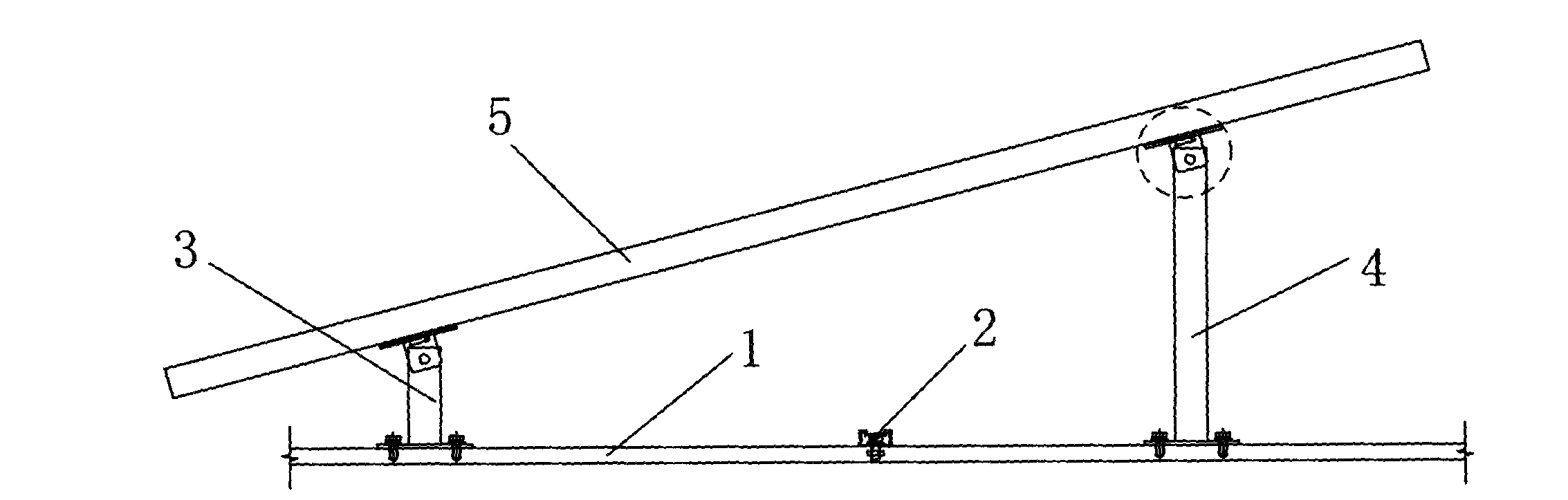
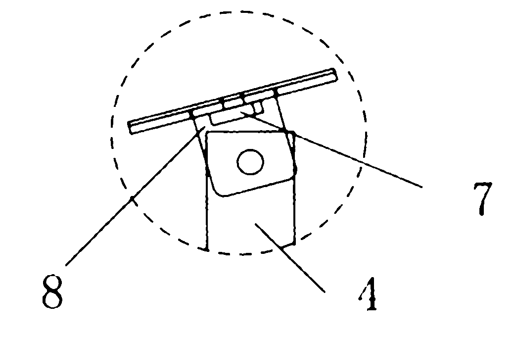
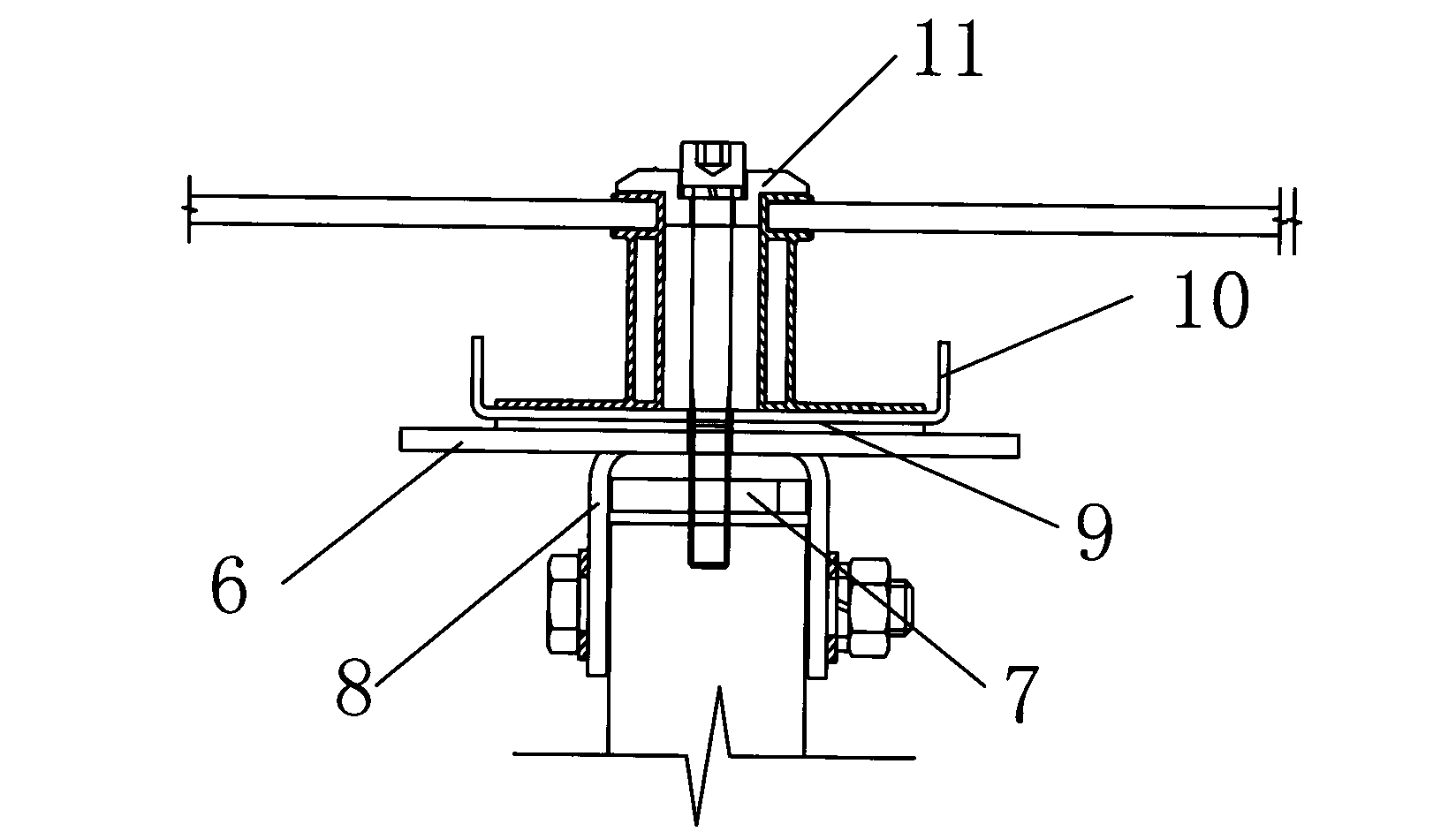
[0023] Such as Figure 1-3 The photovoltaic support on the roof of a double T-plate factory building includes a vertical ground grid 1, and a horizontal ground grid 2 is distributed across the vertical ground grid 1. The difference is that: on one side of the vertical ground grid 1 The front support 3 is distributed, and the rear support 4 is distributed on the other side of the vertical ground net 1. The front support 3, the rear support 4 and the horizontal ground net 2 intersect to form a "well" network, and the positioning is stable. At the same time, in order to connect the corresponding external components, a pressing block component 11 is arranged on the top of the front support 3 and the rear support 4 . An inclined bearing plate 5 is connected to the pressing block assembly 11 by screws. Specifically, the front support 3 can raise the inclined bearing plate 5 to form an inclination angle with the rear support 4 , and the rear support 4 can also raise the inclined bea...


PUM


Abstract

The invention relates to a photovoltaic bracket for a double-T plate plant roof. The photovoltaic bracket comprises a longitudinal ground net, wherein horizontal ground nets are distributed on the longitudinal ground net in a crossed form; the photovoltaic bracket is characterized in that a front support is distributed on one side of the longitudinal ground net; a rear support is distributed on the other side of the longitudinal ground net; and meanwhile, pressing block components are arranged at the tops of the front support and the rear support; and inclined load-bearing plates are connected with the pressing block components through bolts. Thus, a '#' shaped net is formed by the front support, the rear support and the horizontal ground nets in the crossed form; the wind load overturn resistance is high; the longitudinal ground net is paved in advance, so that the roof waterproof material is not damaged; the service life of the plant is not influenced; a connector is adopted, so that the mounting of each component is more firm and safe; the photovoltaic bracket is material-saving and is light in unit weight; the load-bearing risk of the roof is reduced; furthermore, the whole construction is simple; the assembling maneuverability is strong and is not limited by a foundation; and the popularization is benefited.

Description

technical field [0001] The invention relates to a photovoltaic support, in particular to a photovoltaic support on the roof of a factory building with double T boards. Background technique [0002] Affected by the photovoltaic environment, large-scale photovoltaic power station projects have grown rapidly in the past two years. The current situation of my country's large population and small land forces many photovoltaic power stations to develop on the roof of large-scale factories, which are connected to the grid for power generation under the premise of ensuring the normal functions of the factories; currently A considerable part of the industrial plant adopts the double T-plate roof structure. The entire roof is spliced ​​by n pieces of double T-plates. It has strict requirements on the roof's load-bearing and waterproof, which limits the design and installation of the photovoltaic support structure to a certain extent. [0003] However, the existing photovoltaic support ...

Claims


Application Information

Patent Timeline
Patent Type & Authority Applications(China)
IPC IPC(8): E04D13/18E04D12/00H02S20/23
CPCY02B10/12Y02B10/10Y02E10/50
Inventor 王腾强大梽孙利国李定宋卫杰
Owner SUZHOU TALESUN SOLAR TECH CO LTD
Why Eureka
Try Eureka