
Pipeline connector
A technology of connectors and pipes, applied in hand-held tools, workpiece clamping devices, manufacturing tools, etc., can solve the problems of trouble, water leakage at the pipeline interface, misplacement at the R-shaped mouth, etc., to achieve accurate installation, High installation efficiency and good installation quality
- Summary
- Abstract
- Description
- Claims
- Application Information
AI Technical Summary
Problems solved by technology
Method used
Image

Examples
Embodiment Construction
[0012] The present invention will be further described below in conjunction with the accompanying drawings.
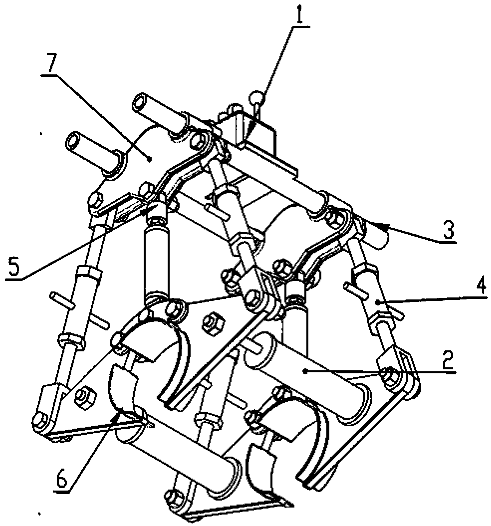
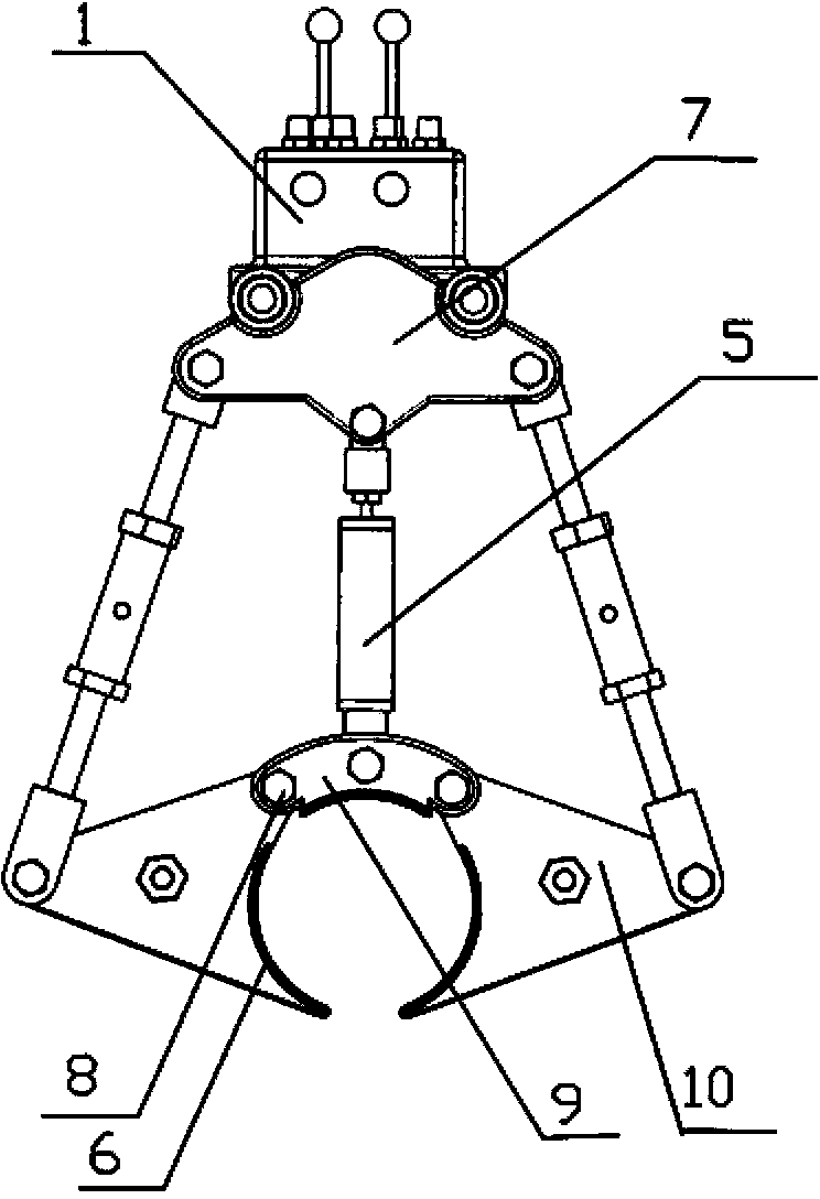
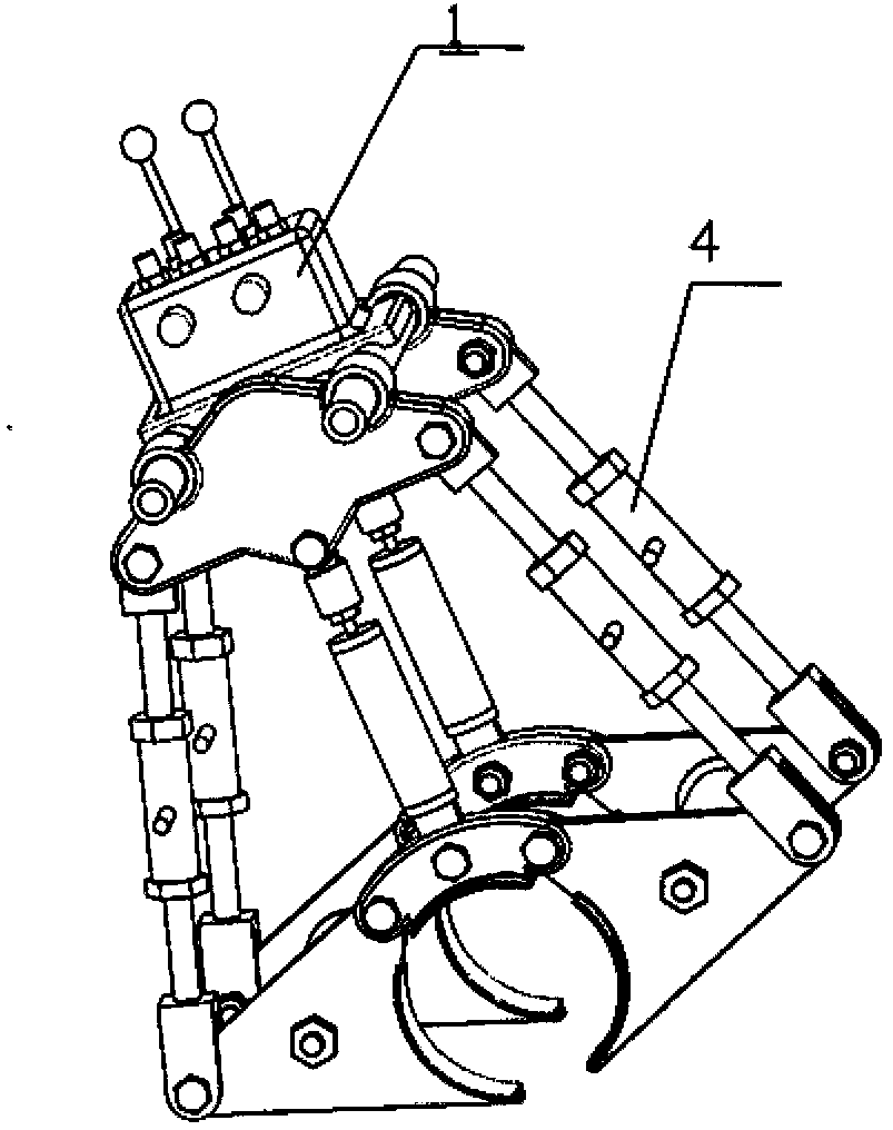
[0013] Depend on Figures 1 to 4 It can be seen that the upper part of the device is a fixed frame 7, and the frame is provided with two front and rear adjustable locks 6, the positions of the two adjustable locks are corresponding, and the center point is on a straight line; The rotating splints 10 on both sides of the pipe device 6 are respectively connected to the above-mentioned fixed frame 7 through the adjustment connecting rod 4, and the upper part of each pipe lock is connected to the fixed frame 7 through the locking arm 5 with a hydraulic cylinder; Both ends of the pipe are connected by hydraulic assembly arms 2, respectively, driven support guide rails 3 are set on both sides of the fixed frame 7, and a hydraulic controller 1 is set on the above-mentioned fixed frame. controller.
[0014] The upper end of the above-mentioned adjustable tube lock is an arc-...
PUM
 Abstract
Description
Claims
Application Information