Optical lens mounting and debugging device

An installation and debugging, optical lens technology, applied in installation, optics, optical components, etc., can solve the problems of lens collision, mirror pollution, low installation efficiency, etc., to improve installation accuracy and installation efficiency, avoid mirror pollution, and installation efficiency. high effect

Pending Publication Date: 2022-02-15
HEFEI I TEK OPTOELECTRONICS CO LTD
View PDF0 Cites 0 Cited by
  • Summary
  • Abstract
  • Description
  • Claims
  • Application Information

AI Technical Summary

Problems solved by technology

At present, the optical lens is generally installed manually. The main disadvantages are: 1. The hand may touch the mirror surface of the optical lens, which may cause pollution of the mirror surface; 2. The lens and the lens barrel are clearance fit, and the manual installation accuracy i

Method used


Image

  • Optical lens mounting and debugging device
  • Optical lens mounting and debugging device
  • Optical lens mounting and debugging device

Examples


Embodiment Construction

[0025] In the following, the technical solution of the present invention will be described in detail through specific embodiments, and many specific details are set forth in the following description so as to fully understand the present invention. However, the present invention can be implemented in many other ways different from those described here, and those skilled in the art can make similar improvements without departing from the connotation of the present invention, so the present invention is not limited by the specific implementation disclosed below.

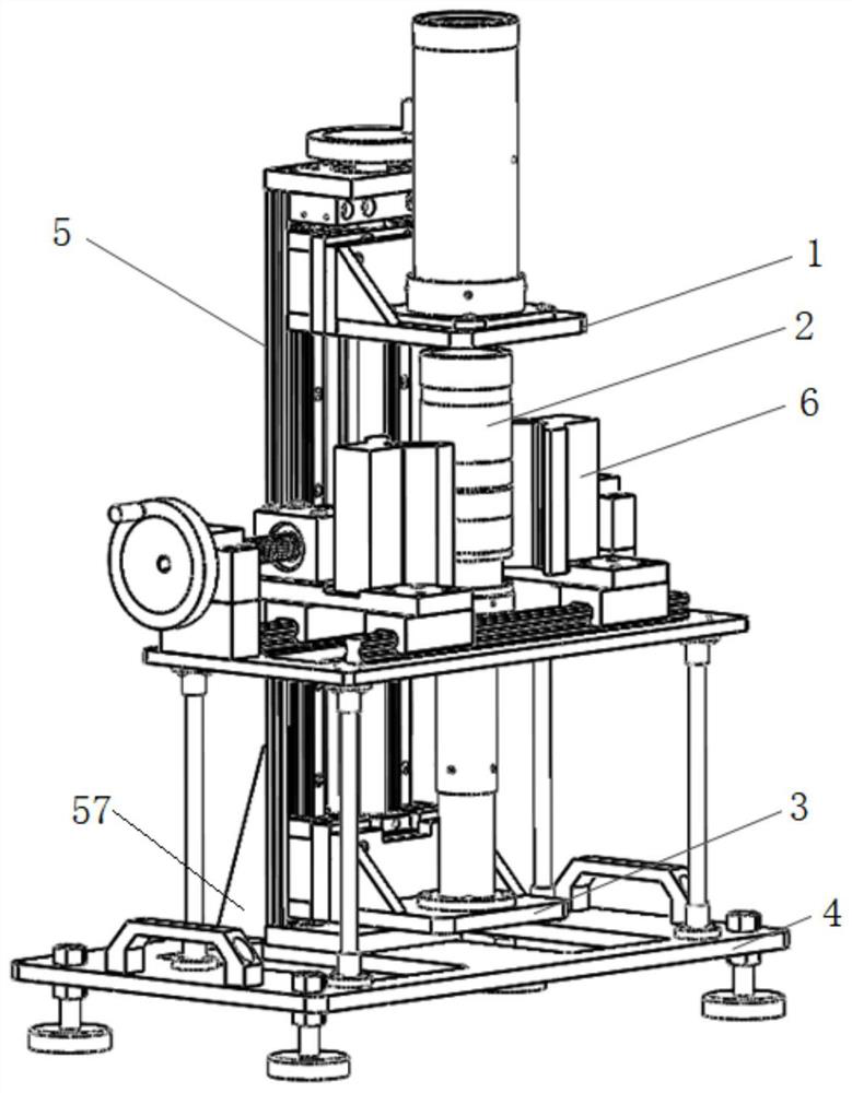
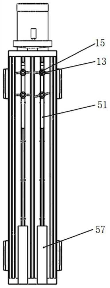
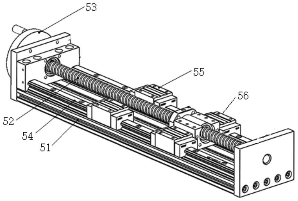
[0026] like Figures 1 to 9 As shown, a device for installing and debugging an optical lens proposed by the present invention includes a lens barrel fixing mechanism 1, an optical lens group 2, a lens advancing mechanism 3, a supporting platform 4 for supporting the two optical lens groups, and a driving platform for driving the lens The transmission mechanism 5 for the movement of the propulsion mechanism 3; the lens ...


PUM


Abstract

The invention discloses an optical lens mounting and debugging device. The device comprises a lens cone fixing mechanism, an optical lens group, a lens propelling mechanism, a bearing platform for supporting an optical lens assembly, and a transmission mechanism for driving the lens propelling mechanism to move; the lens cone fixing mechanism is movably fixed on the transmission mechanism, the transmission mechanism is fixed on the bearing platform, and the lens cone fixing mechanism, the optical lens group and the lens pushing mechanism are sequentially arranged in the axial direction of the optical lens group; and according to the mounting and debugging device, the optical lens assembly is mechanically connected with the lens barrel, the possibility that a hand is in contact with the mirror surface of the optical lens does not exist in the process, so that the possibility that the mirror surface is polluted is avoided, meanwhile, the lens is mechanically mounted, the defects that the manual mounting precision is poor, and the lens is easily clamped in the lens barrel are overcome, meanwhile, accurate installation can be achieved, and the installation precision and the installation efficiency are improved.

Description

technical field [0001] The invention relates to the technical field of optical lens installation, in particular to an optical lens installation and debugging device. Background technique [0002] The lens barrel of the optical lens is long, and the number of lenses in a group is large, which requires high precision and cleanliness during the installation process. At present, the optical lens is generally installed manually. The main disadvantages are: 1. The hand may touch the mirror surface of the optical lens, which may cause pollution of the mirror surface; 2. The lens and the lens barrel are clearance fit, and the manual installation accuracy is poor. , the lens is easy to clamp in the lens barrel; 3. For a long lens, there are multiple lenses inside, and the lenses are easy to collide with each other during the installation process, causing damage; 4. Each lens needs to be installed once, and the installation efficiency is low. Contents of the invention [0003] Base...

Claims


Application Information

Patent Timeline
IPC IPC(8): G02B27/62G02B7/00G02B7/02
CPCG02B27/62G02B7/003G02B7/021
Inventor 王伟李坤韦浩然唐俊峰曹桂平
Owner HEFEI I TEK OPTOELECTRONICS CO LTD
Why Eureka
Try Eureka