Adjusting device of variable valve lift mechanism and variable valve lift mechanism
A valve lift and adjusting device technology, applied in valve devices, machines/engines, mechanical equipment, etc., can solve problems such as increasing the height of the engine, and achieve the effects of fewer parts, simple and reliable structure, and simple structure
- Summary
- Abstract
- Description
- Claims
- Application Information
AI Technical Summary
Problems solved by technology
Method used
Image
Examples
Embodiment 1
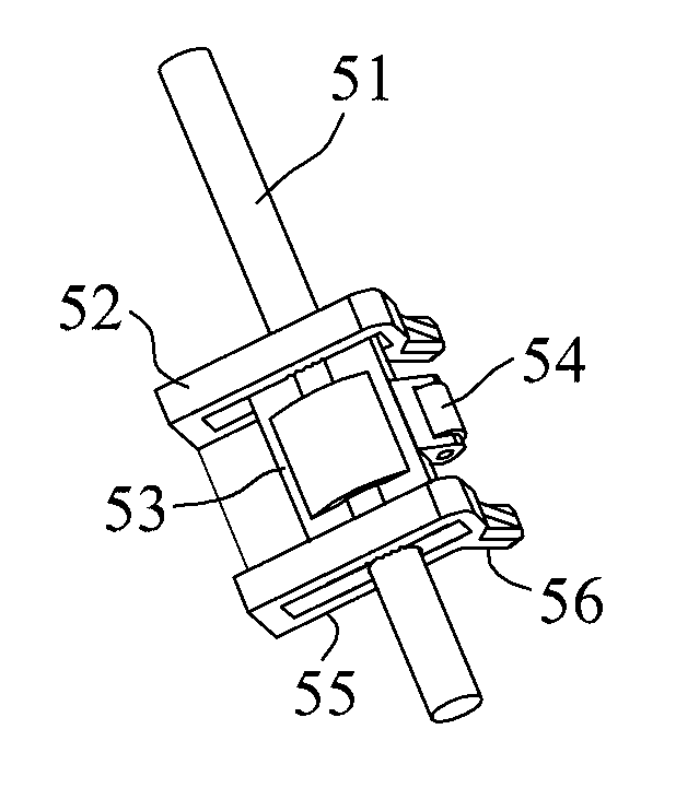
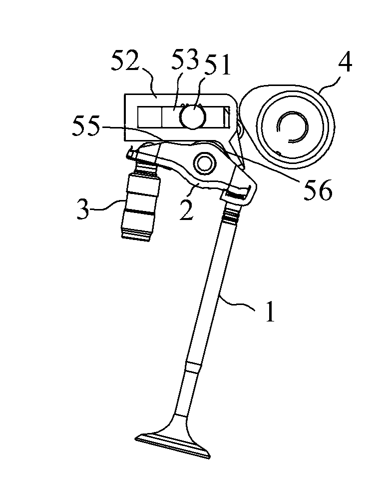
[0023] Such as figure 1 As shown, this embodiment discloses an adjusting device for a variable valve lift mechanism, which is arranged between the cam mechanism and the valve mechanism of the variable valve lift mechanism, and includes a main body 52, a driving mechanism and an external force bearing part. The main body 52 has a first force applying portion 55 and a second force applying portion 56, the second force applying portion 56 is in contact with the first force applying portion 55 and extends obliquely downward, the main body 52 has the first force applying portion 55 alone in contact with the valve mechanism, and a second state in which the second biasing portion 56 is in contact with the valve mechanism alone.
[0024] The driving device applies a rotational driving force to the main body 52, so that the main body 52 can switch back and forth between the first state and the second state. In this embodiment, the driving device specifically includes a rotating shaft 5...
Embodiment 2
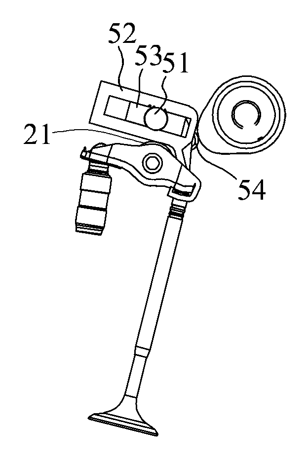
[0027] Such as figure 2 and image 3 As shown, this embodiment discloses a variable valve lift mechanism, including a valve mechanism and a cam mechanism 4. The valve mechanism includes a valve 1, a rocker arm 2 connected to the valve 1, and a hydraulic tappet 3 supporting the rocker arm 2. The rocker arm 2 is provided with a roller 21, the above is the existing structure of the well-known engine, it also includes the adjusting device of the variable valve lift mechanism of the first embodiment, the roller 21 can be connected with the first force applying part 55 Or the second force applying portion 56 contacts, and the cam mechanism 4 contacts the roller 54 , and when the cam mechanism 4 rotates, the roller 54 is pressed down, so that the main body 52 rotates. The angle between the line connecting the axis of the rotating shaft 51 and the roller 21 relative to the line connecting the axis of the rotating shaft 51 and the cam mechanism 4 is 60°-80°, which can ensure the reli...
PUM
 Abstract
Description
Claims
Application Information
 - R&D
- Intellectual Property
- Life Sciences
- Materials
- Tech Scout
- Unparalleled Data Quality
- Higher Quality Content
- 60% Fewer Hallucinations
Browse by: Latest US Patents, China's latest patents, Technical Efficacy Thesaurus, Application Domain, Technology Topic, Popular Technical Reports.
© 2025 PatSnap. All rights reserved.Legal|Privacy policy|Modern Slavery Act Transparency Statement|Sitemap|About US| Contact US: help@patsnap.com


