Energy storage battery of magnetic-suspending flywheel

A flywheel energy storage and battery technology, applied in electrical components, electromechanical devices, electric components, etc., can solve the problems of long charging time, difficult power control, and short power consumption time.

Inactive Publication Date: 2013-04-03
曾涛
View PDF0 Cites 5 Cited by
  • Summary
  • Abstract
  • Description
  • Claims
  • Application Information

AI Technical Summary

Problems solved by technology

Now, the most widely used energy storage battery is undoubtedly the chemical battery, which converts electrical energy into chemical energy storage, and then converts it into electrical energy output. It is cheap and mature in technology, but it has serious pollution, low efficiency, long charging time, and electricity consumption The time is short, and the electric energy is not easy to control during use

Method used


Image

  • Energy storage battery of magnetic-suspending flywheel

Examples


Embodiment Construction

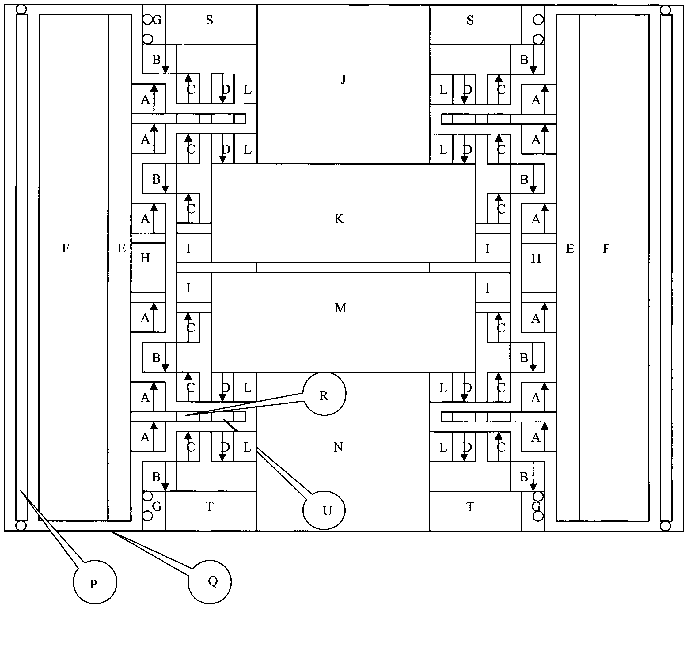
[0023] According to the attached picture:

[0024] 1. A permanent magnet and B permanent magnet have opposite magnetic poles, forming an axial repulsion bearing. At the same time, A permanent magnet and C permanent magnet have inner and outer magnetic poles in the same direction, forming a radial repulsion bearing, so the flywheel rotor is stably suspended outside the stator ;

[0025] 2. H is the magnetic pole fixed on the flywheel rotor, and there is a high-density magnetic field line distribution on the inner edge of the rotor. I is the coil fixed on the stator. H and I form an integrated generator and motor;

[0026] 3. The poles of two sets of C permanent magnets and D permanent magnets are reversed on the upper and lower sides of the stator to form a complete circulation channel of magnetic force lines. The coils on the R and U rotor discs are embedded in the middle of the two sets of C and D permanent magnets. When the flywheel rotor When the position is correct, the m...


PUM


Abstract

The invention relates to an energy storage battery of a magnetic-suspending flywheel. The energy storage battery of the magnetic-suspending flywheel is characterized in that a repulsive magnetic suspending bearing between a rotor and a stator of the magnetic-suspending flywheel through an axial permanent magnet and a radial permanent magnet. The flywheel is suspended in a sealed vacuum environment. 12 permanent magnets are arranged in the middle of the flywheel in an array shape and form an integrated generator/motor with 12 coils in the middle of the stator. A flywheel dynamic stable system generates an induced electromotive force so as to generate a lorentz force opposite to an offset direction through the coils in the upper and lower circular discs of the rotor of the flywheel because the rotor is deviated from a normal position, so that the flywheel returns the normal position. An electronic power control system is integrated in the stator. As the coils and the control system generate heat, a heat pipe radiating system discharges heat to ensure normal operation of the system. As the flywheel which rotates at a high speed is of extremely high energy, once the rotor and the stator abrade to quickly generate high temperature, risk can be controlled within the minimum range by quickly and emergently releasing high pressure nitrogen.

Description

technical field [0001] Among various energy storage technologies, the development speed of chemical energy storage has always been ahead of that of physical energy storage. With the improvement of the energy system's demand for energy storage technology, physical energy storage technology, which has always been known for its low environmental pollution and high operational stability, is being developed. The temperature rises rapidly, among which the flywheel energy storage has the characteristics of fast charging and discharging, and the highest energy density. The flywheel energy storage system is composed of high-speed flywheel, bearing support system, motor, generator, power converter, electronic control system and additional equipment such as vacuum pump and emergency backup bearing. At valley load, the flywheel energy storage system is powered by the power frequency grid to drive the flywheel to rotate at high speed, store energy in the form of kinetic energy, and complet...

Claims


Application Information

Patent Timeline
Patent Type & Authority Applications(China)
IPC IPC(8): H02N15/00H02K7/02
CPCY02E60/16
Inventor 曾涛
Owner 曾涛
Why Eureka
Try Eureka