Oil filter device for range hood

A technology for range hoods and oil nets, which is applied in the direction of removing oil fumes, applications, and household stoves. It can solve problems such as large air intake resistance, increased noise, and clogged dense filter screens, so as to improve the filtering effect, improve the suction efficiency, and The effect of high filtration efficiency

Active Publication Date: 2013-07-31
SAKURA BATH & KITCHEN PRODS CHINA
View PDF6 Cites 0 Cited by
  • Summary
  • Abstract
  • Description
  • Claims
  • Application Information

AI Technical Summary

Problems solved by technology

[0003] The first type: the outer layer adopts the oil guide column, and the inner layer adopts the form of dense filter net. This kind of oil net structure is easy to cause the dense filter net to be clogged, and it is easy to cause the oil net to drip oil when the inclination angle of the oil net is not enough;
[0004] The second type: double-layer tile structure (such as figure 1 As shown), the air intake resistance of this oil net structure is very large, which makes it difficult to increase the air volume of the range hood and makes a lot of noise;
[0005] The third type: double-layer "U"-shaped oil net structure in the same direction (such as figure 2 As shown), this kind of oil net structure is a semi-circular thin plate structure. When the air flow passes by, a large number of eddy currents will be generated on the back of the "U" shape, resulting in a decrease in the suction efficiency of the range hood and an increase in noise;
[0006] The oil net of the range hood is used as the air inlet of the range hood, and it is also the divergence port of the internal noise of the range hood. The above oil net structures do not have the function of noise reduction and noise reduction, resulting in the noise reduction of the range hood.

Method used


Image

  • Oil filter device for range hood
  • Oil filter device for range hood
  • Oil filter device for range hood

Examples


Embodiment

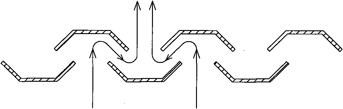
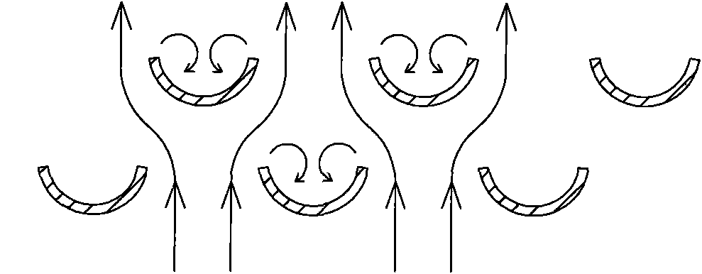
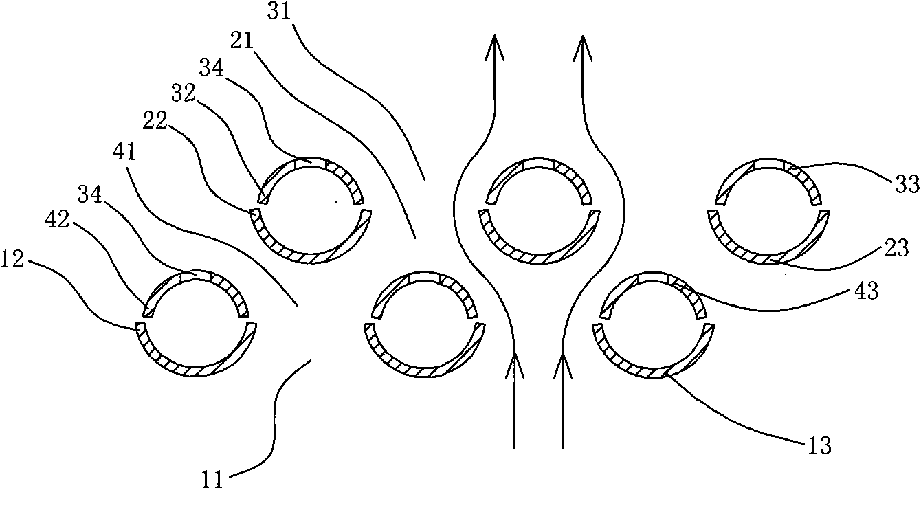
[0029] Embodiment: An oil screen device for a range hood, comprising at least three layers of oil screens, based on the direction of use (the side away from the inside of the range hood is the outside), and the first oil screen from the outside to the inside of the range hood 1 and the second oil net 2 are also provided with a third oil net 3, and the first oil net 1, the second oil net 2 and the third oil net 3 are respectively provided with elongated first, second and third oil nets along the inclined surface of the oil net. 2. Three ventilation holes 11, 21, 31, the first ventilation hole 11 is provided with a closed ring-shaped first flange 12 towards the inside of the range hood, and the second ventilation hole 21 is provided with a " n"-shaped second flange 22, the second flange 22 faces the inside of the range hood, and the side of the third ventilation hole 31 along its length direction and the upper end edge at a relatively higher position are provided with facing towa...


PUM

PropertyMeasurementUnit
widthaaaaaaaaaa

Abstract

The invention discloses an oil filter device for a range hood, characterized by that: the oil filter device is provided with a first oil filter, a second oil filter, and a third oil filter from the outer side to the inner side of the range hood, the first oil filter, the second oil filter, and the third oil filter are respectively provided with a first air vent, a second air vent, and a third airvent, the periphery of the first air vent is provided with a first flanging that is closed annular toward the inner part of the range hood, the second air vent is provided with a second n-shaped flanging that is opened at low end relatively toward the inner part of the range hood, a side of the third air vent along with the length direction and the side of the upper end at a relative high position are respectively provided with third flangings toward the outer part of the range hood, the first and second air vent along with the width direction are arranged with staggering each other, the third air vents are arranged right above the first and second air vent, and the third air vents completely cover one of the first and second air vent corresponding underneath. According to the invention, the wind damage is reduced, the suction efficiency is improved, the noise is reduced, and oil dripping is prevented.

Description

technical field [0001] The invention relates to a range hood, in particular to an oil screen device for the range hood. Background technique [0002] At present, there are mainly the following types of oil screen devices used for range hoods: [0003] The first type: the outer layer adopts the oil guide column, and the inner layer adopts the form of dense filter net. This kind of oil net structure is easy to cause the dense filter net to be clogged, and it is easy to cause the oil net to drip oil when the inclination angle of the oil net is not enough; [0004] The second type: double-layer tile structure (such as figure 1 As shown), the air intake resistance of this oil net structure is very large, which makes it difficult to increase the air volume of the range hood and makes a lot of noise; [0005] The third type: double-layer "U"-shaped oil net structure in the same direction (such as figure 2 As shown), this kind of oil net structure is a semi-circular thin plate s...

Claims


Application Information

Patent Timeline
Patent Type & Authority Patents(China)
IPC IPC(8): F24C15/20B01D46/12
Inventor 廖金柱
Owner SAKURA BATH & KITCHEN PRODS CHINA
Why Eureka
Try Eureka