Air port converging mechanism of backrest ventilating fan and automobile seat

A ventilation fan and tandem technology, which is applied to vehicle seats, seat heating/ventilation devices, vehicle components, etc., can solve the problems of long air paths, unfavorable seat ventilation, and high wind damage.

Active Publication Date: 2020-10-20
LANGFANG JINSESHIGUANG TECH LTD
View PDF13 Cites 0 Cited by
  • Summary
  • Abstract
  • Description
  • Claims
  • Application Information

AI Technical Summary

Problems solved by technology

The ventilation fan of the existing seat back is installed on the frame wire spring frame of the seat back. During installation, it is necessary to avoid the steel wire of the frame wire spring frame at a fixed point. A common method is to use a traditional air guide structure to bypass the frame wire spring frame It communicates with the air inlet of the ventilation fan. This method has a long air path and high wind loss; another common method is to set an intermediate structure between the air guide structure and the ventilation fan. The intermediate structure must avoid the frame wire spring frame The steel wire passes through the blank space formed between the steel wire bending structures. The air path area of ​​the intermediate structure is limited by the blank space and will be lower than the area of ​​the fan air inlet. On the one hand, the components and costs are increased, and on the other hand, wind resistance is also generated. , not conducive to seat ventilation

Method used


Image

  • Air port converging mechanism of backrest ventilating fan and automobile seat
  • Air port converging mechanism of backrest ventilating fan and automobile seat
  • Air port converging mechanism of backrest ventilating fan and automobile seat

Examples


Embodiment 1

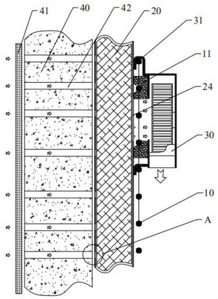
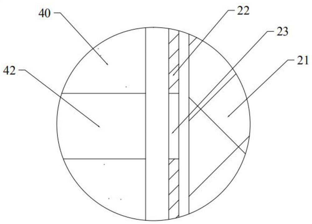
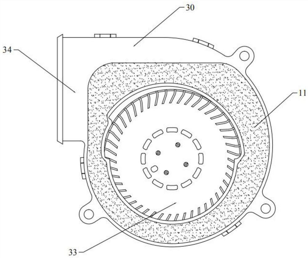
[0030] Please refer to figure 1 and figure 2 , the present embodiment provides a tuyere confluence mechanism of a backrest ventilation fan, including a frame wire spring frame 10; one side of the frame wire spring frame 10 is provided with an air guide structure, and the other side is provided with a ventilation fan 30; In the embodiment, the air guide structure is an air guide bag 20. In other embodiments of the present application, the air guide structure can also be set to any of the following structures: a sealing layer plus a foamed internal channel structure, and a sealed air guide inside the sealing layer. layer (commonly used three-dimensional knitted mesh cloth or a plastic plate with protrusions), or a foaming structure can be provided on the outside of the side of the air guide bag surface cover with the total air path interface 24, on the foaming structure A through hole is opened to communicate with the main air path interface and the air inlet or air outlet of ...

Embodiment 2

[0036]This embodiment provides another tuyere confluence mechanism of the backrest ventilation fan. The similarities between this embodiment and Embodiment 1 will not be repeated, and the difference is that one end of the first flexible wind-blocking cushion layer 11 is fixedly connected to On the side where the wind guide bag 20 has the total air path interface 24, since the first flexible wind blocking cushion layer 11 is a compressible elastic material, it can avoid the steel wire of the frame wire spring frame 10 at a fixed point. The free end of a flexible wind-blocking cushion layer 11 can pass through the gap between the adjacent steel wires and be directly compressed with the ventilation fan 30, and can also be partially compressed on the steel wires to undergo elastic deformation, that is, it is bonded and merged with the steel wires. In the depressed state, the other part is compressed on the ventilation fan 30 and undergoes a small elastic deformation, and because th...

Embodiment 3

[0038] Please refer to image 3 , this embodiment provides another tuyere confluence mechanism of the backrest ventilation fan. The similarities between this embodiment and Embodiment 1 will not be described in detail. There is also a second flexible wind-blocking cushion layer 12 in between; the second flexible wind-blocking cushion layer 12 is a compressible elastic wind-blocking material, and a second air path hole corresponding to the first air path hole is opened on it; One end of the second flexible wind-blocking cushion layer 12 is fixedly connected to the side of the air-guiding bag 20 with the main air-way interface 24, and the other end is used for extrusion-tight fit with the first flexible wind-blocking cushion layer 11 , that is, the first flexible wind-blocking cushion layer 11 and the second flexible wind-blocking cushion layer 12 are disposed opposite to each other between the ventilation fan 30 and the wind guide bag 20 . In this embodiment, one end of the fi...


PUM


Abstract

The application provides an air port converging mechanism of a backrest ventilation fan. The mechanism comprises a frame wire spring frame, an air guide structure is arranged on one side of the framewire spring frame, and a ventilation fan is arranged on the other side of the frame wire spring frame; a main air path connector is formed in the side, close to an air inlet of the ventilation fan, ofthe air guide structure. A first flexible air blocking cushion layer is arranged between the air guide structure and the ventilation fan in an extruding manner; the first flexible air blocking cushion layer is made of a compressible elastic wind blocking material, and one end of the first flexible air blocking cushion layer is fixedly connected to the air guide structure or the ventilation fan; afirst air path hole is formed in the first flexible air blocking cushion layer; the airflow of the main air path connector enters an air inlet of the ventilation fan through the first air path hole.The air port converging mechanism of the backrest ventilating fan is low in cost, short in air path and low in air loss, a steel wire of the frame wire spring frame does not need to be avoided at a fixed point during use; meanwhile, air path sealing between the air guide structure and the air inlet of the ventilating fan can be achieved, air leakage and air flow loss are avoided, and the reliability of a seat ventilating air path is guaranteed.

Description

technical field [0001] The present application relates to the technical field of car seats, in particular to an air outlet confluence mechanism of a back ventilation fan and a car seat. Background technique [0002] In recent years, with the advancement of car seat comfort system technology, seats with suction-type ventilation devices have become more and more accepted by the public. The ventilation fan of the existing seat back is installed on the frame wire spring frame of the seat back. During installation, it is necessary to avoid the steel wire of the frame wire spring frame at a fixed point. A common method is to use a traditional air guide structure to bypass the frame wire spring frame It communicates with the air inlet of the ventilation fan. This method has a long air path and high wind loss; another common method is to set an intermediate structure between the air guide structure and the ventilation fan. The intermediate structure must avoid the frame wire spring ...

Claims


Application Information

Patent Timeline
Patent Type & Authority Applications(China)
IPC IPC(8): B60N2/56
CPCB60N2/5657
Inventor 张海涛
Owner LANGFANG JINSESHIGUANG TECH LTD
Why Eureka
Try Eureka