
Full-automatic PCB (printed circuit board) positioning clamp

A PCB board and positioning fixture technology, applied in the direction of assembling printed circuits with electrical components, can solve the problems of time-consuming positioning and clamping, low working efficiency of the entire production line, poor stability, etc., to improve production efficiency and reliability. And the effect of convenient positioning and clamping, fast and accurate positioning and clamping

Active Publication Date: 2013-04-03
广州弘高科技股份有限公司
View PDF4 Cites 41 Cited by
  • Summary
  • Abstract
  • Description
  • Claims
  • Application Information

AI Technical Summary

Problems solved by technology

With the development of the electronics industry, the requirements for the positioning and clamping of PCB boards in the SMT process are getting higher and higher. At present, most of the fixing and clamping of PCB boards in the electronics industry are manually positioned and clamped. Not only the positioning error is large, The stability is poor, and the positioning and clamping takes a long time, which makes the work efficiency of the whole production line not high. Therefore, a pair of positioning fixtures can automatically enter and exit the board and quickly, accurately, reliably and conveniently position and clamp the PCB board. It plays a great role in improving the efficiency of the entire production line

Method used


Image

  • Full-automatic PCB (printed circuit board) positioning clamp
  • Full-automatic PCB (printed circuit board) positioning clamp
  • Full-automatic PCB (printed circuit board) positioning clamp

Examples


Embodiment Construction

[0017] The structure and operation steps of the fully automatic PCB board positioning jig of the present invention will be described in detail below with reference to the accompanying drawings.

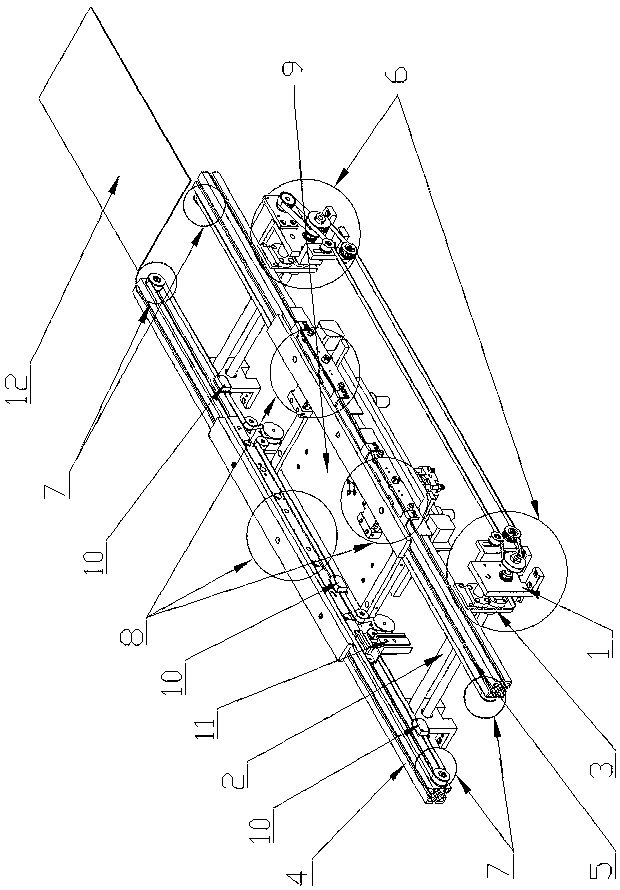
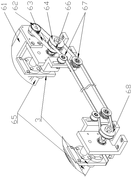
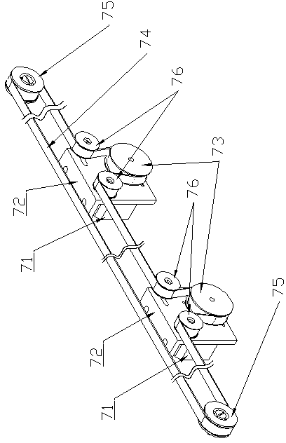
[0018] The fully automatic PCB board positioning fixture of the present invention, the fully automatic PCB board positioning fixture of the present invention, comprises a support base 1, a support rod 2, a sliding support plate 3, a fixed side rail 4, a moving side rail 5, a width adjustment mechanism 6, a conveying Mechanism 7, clamping mechanism 8, top plate mechanism 9, detection mechanism 10 and positioning mechanism 11, wherein the support rod 2 and the width adjustment mechanism 6 are installed on the opening provided on the side of the support base 1, and the fixed side rail 4 is fixed on On the support seat 1, the sliding support plate 3 is slidably connected with the support rod 2, and the mobile side rail 5 is fixed on the sliding support plate 3, the sliding support plate 3 ...


PUM


Abstract

The invention provides a full-automatic PCB (printed circuit board) positioning clamp. The full-automatic PCB positioning clamp comprises a support seat, a support rod, a sliding support plate, a fixed-side railing, a movable-side railing, width adjusting mechanisms, conveying mechanisms, clamping mechanisms, a top plate mechanism, a detecting mechanism and a positioning mechanism, wherein the support rod and the width adjusting mechanisms are assembled on holes reserved on the lateral side of the support seat, the fixed-side railing is fixed on the support seat, the sliding support plate is slidably connected with the support rod, the movable-side railing is fixed on the sliding support plate which is connected with the width adjusting mechanisms, the conveying mechanisms are mounted on the inner sides of the fixed-side railing and the movable-side railing to form a PCB delivery rail, the clamping mechanisms are fixed on the fixed-side railing and the movable-side railing, the detecting mechanism is mounted on the fixed-side railing, and the positioning mechanism used for positioning the PCB when entering is fixed at a positioning position on the fixed-side railing. The full-automatic PCB positioning clamp can quickly automatically deliver the PCB, and can position and clamp the PCB accurately, reliably and conveniently, and production efficiency of an assembly line is improved.

Description

technical field [0001] The invention relates to a fully automatic PCB board positioning fixture, in particular to a fully automatic PCB board positioning fixture used in the SMT automatic assembly and printing process. Background technique [0002] The positioning fixture of the PCB board is an important part of the SMT automatic assembly and printing process, especially in the printing, placement and testing parts. With the development of the electronics industry, the requirements for the positioning and clamping of PCB boards in the SMT process are getting higher and higher. At present, most of the fixing and clamping of PCB boards in the electronics industry are manually positioned and clamped. Not only the positioning error is large, The stability is poor, and the positioning and clamping takes a long time, which makes the work efficiency of the whole production line not high. Therefore, a pair of positioning fixtures can automatically enter and exit the board and quickl...

Claims


Application Information

Patent Timeline
IPC IPC(8): H05K3/30
Inventor 肖曙红汤雄
Owner 广州弘高科技股份有限公司
Learn More