
Tool

A tooling, to-be-processed technology, used in positioning devices, manufacturing tools, metal processing equipment, etc., can solve cumbersome problems and achieve the effect of improving efficiency and accuracy, accurate positioning and clamping

Active Publication Date: 2013-04-10
江阴市惠尔信精密装备股份有限公司
View PDF6 Cites 3 Cited by
  • Summary
  • Abstract
  • Description
  • Claims
  • Application Information

AI Technical Summary

Problems solved by technology

[0003] The purpose of the present invention is to overcome the cumbersome defect of fixing and dismounting parts to be processed by the tooling in the prior art, and provide a tooling with reasonable structure and convenient disassembly and assembly.

Method used


Image

  • Tool
  • Tool
  • Tool

Examples


Embodiment Construction

[0015] The specific implementation manners of the present invention will be further described below in conjunction with the drawings and examples. The following examples are only used to illustrate the technical solution of the present invention more clearly, but not to limit the protection scope of the present invention.

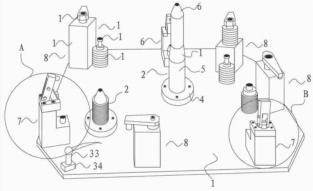
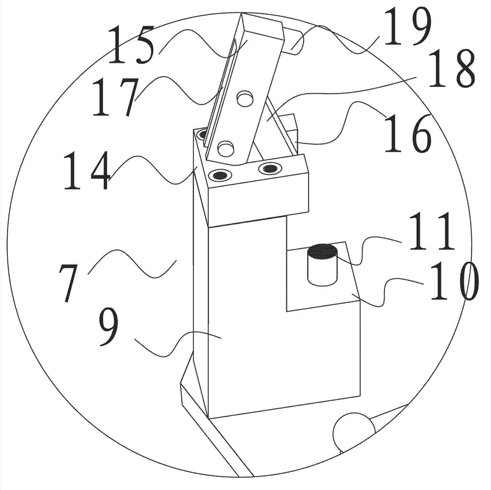
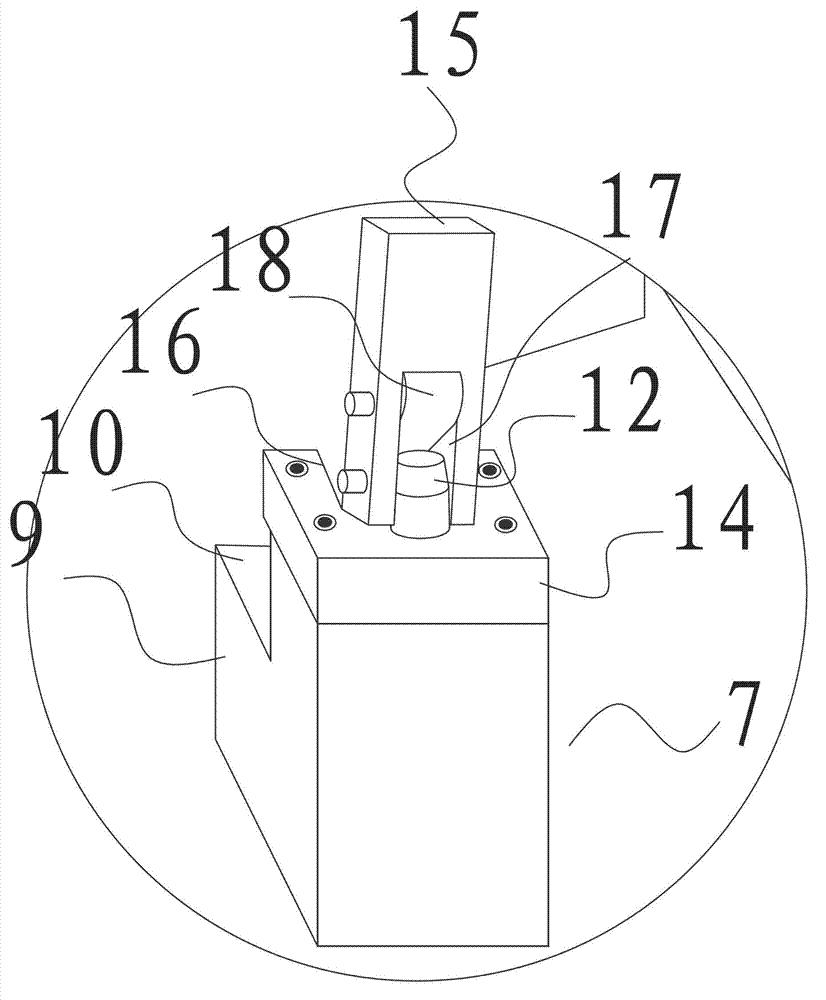
[0016] Such as Figure 1-Figure 3 As shown, a tooling includes a base plate 1, a positioning column 2 and a fixing device arranged on the base plate 1, the positioning column 2 is adapted to the positioning hole of the part to be processed, and the fixing device includes a fixing device for fixing the part to be processed The pressing device 7 and the clamping device 8 matched with each other;

[0017] The positioning column 2 includes a cylindrical positioning body 5 and a tapered guide end 6 arranged on the upper end of the cylindrical positioning body 5. The base plate 1 is provided with a disc-shaped column seat 4, and the bottom end of the positioning...


PUM


Abstract

The invention discloses a tool, which comprises a bottom plate, positioning columns and fixing devices, wherein the positioning columns and the fixing devices are arranged on the bottom plate; the positioning columns are matched with positioning holes for a component to be machined; and the fixing devices comprise pressing devices and clamping devices which are matched with a fixing end of the component to be machined. By arranging a plurality of positioning columns and clamping components on the tool, the component to be machined can be quickly and accurately positioned and clamped, and the machining efficiency and accuracy are improved. The tool is particularly suitable for fixing a plate-like steel member with a through hole in the middle part.

Description

technical field [0001] The invention relates to a tool. Background technique [0002] In traditional robotic arm processing, fixing holes are generally processed on the robotic arm parts, and then the robotic arm is fixed on a certain tooling equipment through bolts, and then processed. This processing method requires repeated disassembly of the bolts, and the operation is cumbersome. At the same time, such processing accuracy is low, which cannot meet the requirements of high efficiency and high precision of machining at the present stage. Contents of the invention [0003] The purpose of the present invention is to overcome the cumbersome defects of the tooling in the prior art for fixing and dismounting parts to be processed, and to provide a tooling with reasonable structure and convenient assembly and disassembly. [0004] In order to achieve the above object, the technical solution of the present invention is to provide a tooling, the tooling includes a base plate a...

Claims


Application Information

Patent Timeline
IPC IPC(8): B23Q3/00
Inventor 徐惠民缪国清
Owner 江阴市惠尔信精密装备股份有限公司
Learn More