
Surface treatment device

A surface treatment device and a technology for processing objects, which are applied to used abrasive treatment devices, abrasives, metal processing equipment, etc., and can solve problems such as dispersion and leakage of projectile materials

Active Publication Date: 2015-12-16
SINTOKOGIO LTD
View PDF9 Cites 0 Cited by
  • Summary
  • Abstract
  • Description
  • Claims
  • Application Information

AI Technical Summary

Problems solved by technology

[0004] However, in such devices there are cases where the projectile material disperses and leaks from the device

Method used


Image

  • Surface treatment device
  • Surface treatment device
  • Surface treatment device

Examples


Embodiment Construction

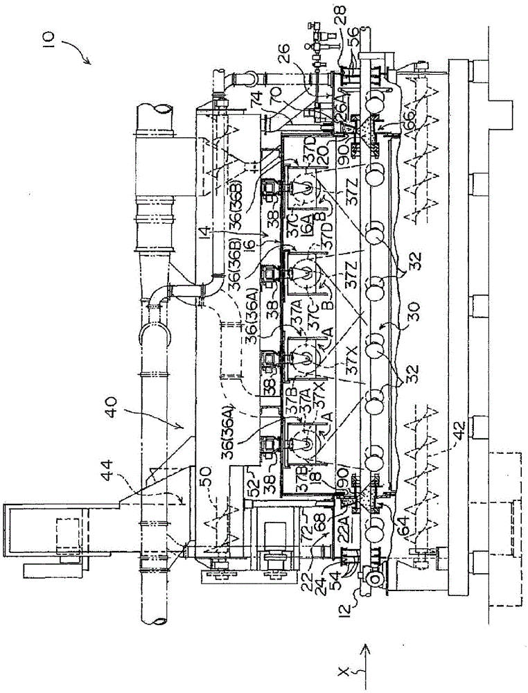
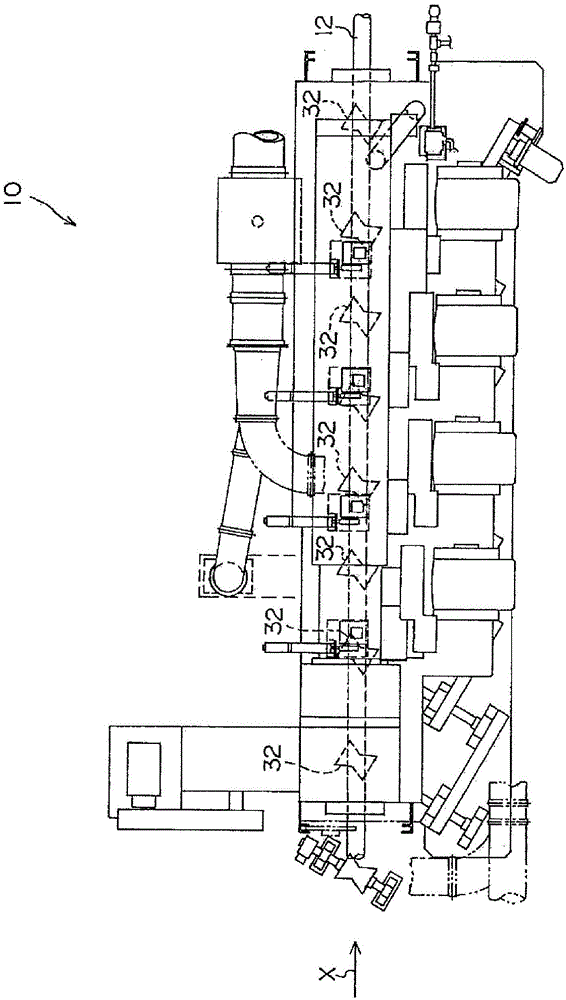
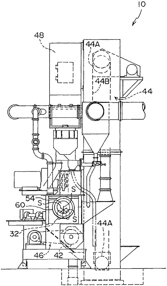
[0029] use Figure 1 to Figure 6 The shot blasting apparatus which is a surface treatment apparatus which concerns on one Embodiment of this invention is demonstrated. figure 1 The shot blasting device 10 is shown in a front view, figure 2 The shot blasting device 10 is shown in a top view, image 3 The shot blasting device 10 is shown in right side view.

[0030]In addition, the shot blasting apparatus 10 which concerns on this embodiment makes the rod-shaped material 12 the object to be processed. Arrow X appropriately shown in the drawing indicates the conveyance direction of the rod-shaped material 12 (hereinafter referred to as "rod-shaped material conveyance direction").

[0031] Such as figure 1 As shown, the shot blasting device 10 has a chamber 14 . Inside the chamber main body 16 constituting most of the chamber 14, a projection chamber (also referred to as a "processing chamber" or a "blasting chamber") for surface processing of the rod-shaped material 12 is f...


PUM


Abstract

In order to obtain a surface treatment device capable of preventing or suppressing the leakage of a projection material and the like from within the device, seal cylindrical portions (64, 66) are mounted to a carry-in port (18) and a carry-out port (20) of a cabinet body (16) to constitute part of a transfer passage for a bar (12). The seal cylindrical portions (64, 66) are formed in the shape of a cylinder to enable the bar (12) to pass through the inside of the cylinder, a projection material (90) is poured thereinto from holes (64A, 66A) formed in the top thereof, and the projection material (90) is stored in the inside of the cylinder. Consequently, even if the projected projection material scatters, the projection material is blocked by the projection material (90) stored in the seal cylindrical portions (64, 66).

Description

technical field [0001] The present invention relates to a surface treatment device for performing surface treatment by projecting a projectile onto the surface of an object to be treated such as a rod-shaped material. Background technique [0002] Among the surface treatment apparatuses, there is, for example, a surface treatment apparatus that carries an object to be processed into a chamber and performs shot blasting by projecting a material onto the surface of the object to be processed (for example, refer to Patent Document 1). [0003] Patent Document 1: Japanese Unexamined Patent Application Publication No. 2003-334759 [0004] However, in such devices, there are cases where the projectile material disperses and leaks from the device. Contents of the invention [0005] In view of the above facts, an object of the present invention is to obtain a surface treatment device capable of preventing or suppressing leakage of projectile materials and the like from the device...

Claims


Application Information

Patent Timeline
Patent Type & Authority Patents(China)
IPC IPC(8): B24C3/32B24C9/00
CPCB24C1/086B24C3/14
Inventor 岩田恭一
Owner SINTOKOGIO LTD
Learn More