
Vacuum degassing device of glass melt

A technology of vacuum degassing device and glass melt, applied in glass furnace equipment, glass manufacturing equipment, manufacturing tools, etc., can solve the problems of glass melt leakage, erosion of thermal insulation materials, shortening the service life of vacuum degassing device, etc.

Inactive Publication Date: 2006-01-18
ASAHI GLASS CO LTD
View PDF1 Cites 0 Cited by
  • Summary
  • Abstract
  • Description
  • Claims
  • Application Information

AI Technical Summary

Problems solved by technology

But even with denser refractory bricks used as refractory bricks for these parts, there is still the problem of glass melt leaking through the gaps in the joints, dissolving and eroding the insulating material behind the supporting refractory bricks or dense refractory bricks, so that Brick components in the glass melt will reduce the quality of the product
Moreover, especially in the vacuum degasser 110, due to the internal decompression of the vacuum housing 112, the leakage of the glass melt will be significant, and the supporting refractory bricks or heat insulating materials will be eroded by the glass melt, and the vacuum degasser will be shortened. own service life

Method used


Image

  • Vacuum degassing device of glass melt
  • Vacuum degassing device of glass melt
  • Vacuum degassing device of glass melt

Examples


Embodiment Construction

[0026] Now, the vacuum degassing apparatus for glass melt of the present invention will be described in detail with reference to preferred embodiments shown in the accompanying drawings.

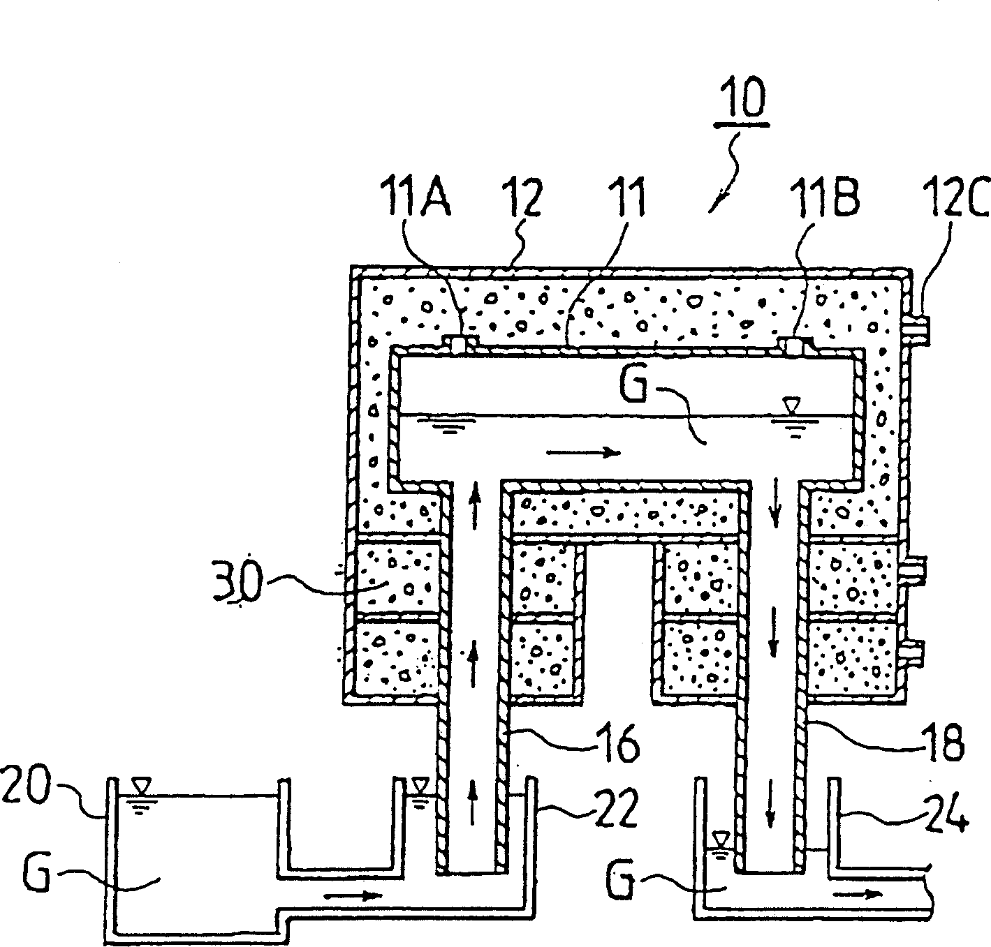
[0027] like figure 1 The vacuum degassing device 10 for the glass melt in the shown embodiment comprises a substantially right-angled vacuum housing 12 made of stainless steel, a vacuum degassing tank horizontally placed in the vacuum housing 12 and having a rectangular cross-sectional shape 11. An ascending pipe 16 and a descending pipe 18 vertically mounted on the vacuum housing 12 , the respective upper ends of the ascending pipe and the descending pipe are connected to the right end and the left end of the vacuum degassing tank 11 .

[0028] The vacuum degassing device 10 used in this method is used in the process of vacuum degassing the glass melt G in the melting tank 20, and the degassed glass melt is continuously supplied to the subsequent treatment tank (not shown) , such as a for...


PUM


Abstract

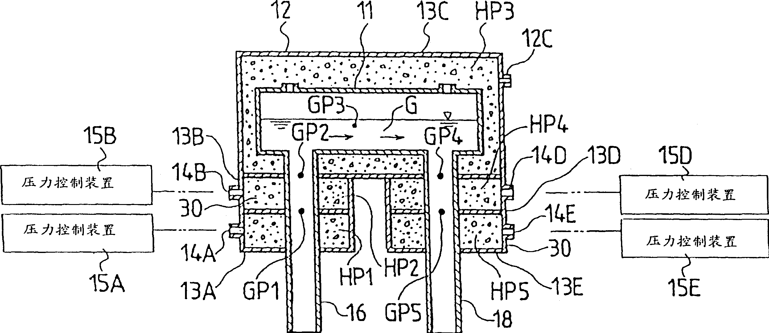
A vacuum degassing apparatus for molten glass, comprising: a vacuum housing which is evacuated to be depressurized therein; a vacuum degassing vessel which is provided in the vacuum housing to vacuum-degas molten glass; an uprising pipe which connects to the vacuum degassing vessel, and sucks and draws up undegassed molten glass to introduce the undegassed molten glass into the vacuum degassing vessel; and a downfalling pipe which connects to the vacuum degassing vessel and draws down the degassed molten glass from the vacuum degassing vessel to discharge the degassed molten glass; wherein said vacuum housing has an accommodating portion to accommodate said uprising pipe and an accommodating portion to accommodate said downfalling pipe, at least one of which is divided horizontally into a plurality of sections, to form a plurality of divided rooms juxtaposed in the vertical direction, and the respective divided rooms are provided with pressure control means to control the pressures of the respective divided rooms independently.

Description

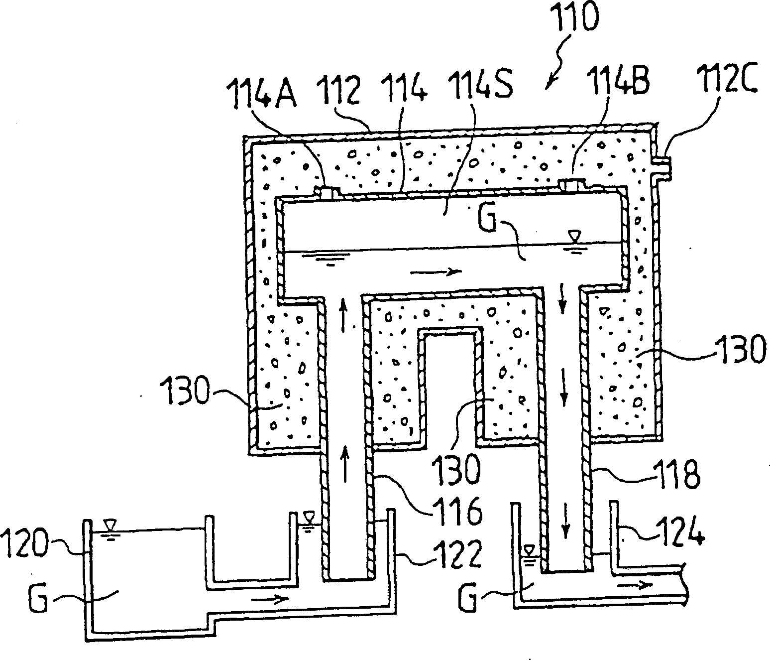
technical field [0001] The present invention relates to a vacuum degassing device for glass melt, which can remove air bubbles in continuously supplied glass melt. Background technique [0002] In order to improve the quality of shaped glass products, a vacuum degassing device that can remove the bubbles generated in the glass melt before the glass melt melted in the melting tank is formed by the forming device has been proposed. [0003] image 3 The vacuum degassing device 110 shown is used in the process of vacuum degassing the glass melt in the melting tank 120, and then continuously supplying it to the subsequent processing tank. The vacuum degassing apparatus 110 includes a vacuum degassing tank 114 and an ascending pipe 116 and a descending pipe 118, both of which are connected to respective end portions of the vacuum degassing tank 114 in a vertical direction. The vacuum degassing tank 114, the riser 116 and the downcomer 118 are housed in the vacuum housing 112 tha...

Claims


Application Information

Patent Timeline
Patent Type & Authority Patents(China)
IPC IPC(8): C03B5/225
CPCC03B5/2252C03B5/225
Inventor 坂井光美佐佐木道人伊藤肇
Owner ASAHI GLASS CO LTD
Learn More