Protector for a leading edge of an airfoil

a technology for protecting the leading edge of an airfoil and a helicopter, which is applied in the field of airfoils, can solve the problems of reducing the operational life of the rotor blade, negative affecting the rotor blade, and erosion of the leading edg

Inactive Publication Date: 2010-01-14
UNITED PROTECTIVE TECH
View PDF7 Cites 43 Cited by
  • Summary
  • Abstract
  • Description
  • Claims
  • Application Information

AI Technical Summary

Benefits of technology

[0019]In an embodiment, the invented protector for an airfoil, comprises an energy absorption member; a first adhesive bond layer attached to said energy absorption member wherein said first adhesive bond layer is adapted for attaching said protector to a leading edge of said airfoil and having a bonding strength between said energy absorption member and said airfoil such that said protector is manually removable from said leading edge; an erosion resistant member forming the outer surface of said protector and providing erosion resistance against environmental effects, wherein said erosion resistant member is made of a metal or alloy; a second adhesive bond layer sandwiched between said energy absorption member and said erosion resistant member, wherein said adhesive bond layer bonds said erosion resistant member to said energy absorption member; wherein environmental impact forces against said erosion resistant member are at least partially dissipated by said energy absorption member prior to being transferred to said airfoil; and wherein said protector has a flexibility whereby it can be manually pressed against said leading edge and conformed to a contour of said leading edge.
[0020]In an embodiment, the invented protector is applied to an airfoil and comprises a rotor blade having a leading edge; an energy absorption member; a first adhesive bond layer attaching said energy absorption member to said leading edge and having a bonding strength between said energy absorption member and said airfoil such that said protector is manually removable from said leading edge; an erosion resistant member forming the outer surface of said protector and providing erosion resistance against environmental effects, wherein said erosion resistant member is made of a metal or alloy; a second adhesive bond layer sandwiched between said energy absorption member and said erosion resistant member, wherein said adhesive bond layer bonds said erosion resistant member to said energy absorption member; wherein environmental impact forces against said erosion resistant member are at least partially dissipated by said energy absorption member prior to being transferred to said airfoil; and wherein said protector has a flexibility whereby it can be manually pressed against said leading edge and conformed to a contour of said leading edge.
[0021]In an embodiment, the invented protector is a protector for an airfoil, comprising an energy absorption member; a first adhesive bond layer attached to said energy absorption member wherein said first adhesive bond layer is adapted for attaching said protector to a leading edge of said airfoil and having a bonding strength between said energy absorption member and said airfoil such that said protector is manually removable from said leading edge; an erosion resistant member forming the outer surface of said protector and providing erosion resistance against environmental effects, wherein said erosion resistant member is made of a metal or alloy; a second adhesive bond layer sandwiched between said energy absorption member and said erosion resistant member, wherein said adhesive bond layer bonds said erosion resistant member to said energy absorption member; a diamond film layer attached to a major surface of said erosion resistant member; wherein environmental impact forces against said diamond film are at least partially dissipated by said energy absorption member prior to being transferred to said airfoil; and wherein said protector has a flexibility whereby it can be manually pressed against said leading edge and conformed to a contour of said leading edge.

Problems solved by technology

Practically, however, helicopters are operated in a wide variety of environmental conditions which negatively affect their rotor blades.
For example, rain and environments having abrasive particulate matter such as sand negatively affects rotor blades through erosion wear and impact forces; dramatically reducing the rotor blades operational life.
Experience has shown that rain impinging upon the leading edges of rotating rotor blades cause erosion wear of the leading edges.
Additionally, impact forces due to the mass of the rain drops are transferred into the rotor blades which can damage the intrinsic de-icing system and bond lines of the blade spars.
Environmental conditions having particulate matter, such as sand, present a different set of problems for rotor blades.
Sand typically does not have as great of a mass as rain, however, it is extremely abrasive and quickly erodes the rotor blades leading edges.
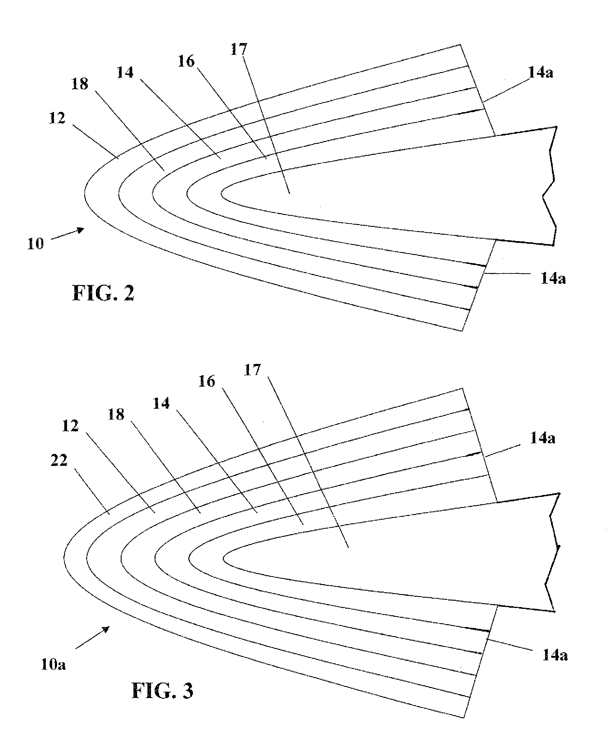
These leading edge caps provide good wear resistance against rain impacts encountered during helicopter flight operations, but are subject to quick erosion as a result of particulate impacts, typically in the form of sand, and provide little benefit against energy transfer from large particle impacts, e.g., impact forces due to rain.
Moreover, as experience in Desert Storm revealed, nickel and titanium leading edge caps experienced undesired erosion wear when subjected to operations in a sand particle environment such as a desert.
Not only were the leading edge caps subjected to rapid erosion wear as a result of forward flight through sand storms, but also as a result of hover operations, e.g., take-offs and landings, due to particulate sand motion caused by rotor blade vortices, i.e., downwash.
Sand erosion wear of the nickel leading edge caps quickly leads to the need to replace such caps to maintain desired flight characteristics of the rotor blades.
However, inasmuch as the nickel leading edge caps comprise an integral part of the rotor blade, i.e., such caps are adhesively bonded to the composite infrastructure, replacement of the eroded nickel edge caps is not a field level repair.
Such repair is expensive and results in significant downtime for the affected helicopter.
Further, the cost of elastomeric sacrificial tape coatings is significantly less than nickel leading edge caps.
While the use of elastomeric sacrificial tape extends the useful life of the nickel leading edge caps with respect to sand particle erosion, the maintenance cycle for replacement of worn elastomeric sacrificial tape makes the use of such tape a less than optimal solution.
Additionally, sand particles may become embedded in the tape thereby adding mass and surface roughness to the leading edge which can affect rotor blade balance and flight performance.
Still another deficiency is that hydrolysis can occur when elastomeric tape is subjected to rain impacts, ultimately causing chucks of the elastomeric tape to break-off.
Another disadvantage is that the mass of the elastomeric tape can cause the tape to debond from the rotor blade during flight.
Furthermore, due to the mass of the elastromeric tape, its application may require time-consuming tracking and balancing of the rotors blades.
These problems may be acerbated due to inconsistent application of the tape to the rotor blade and uneven distribution of mass throughout the elastomeric tape.
Under the aforementioned conditions, the useful erosion protection lifetime of elastomeric sacrificial tape is significantly reduced.
Notwithstanding the advantages stated in the Eaton et al. patent, ceramics have inherent disadvantages.
One downside is that ceramics may be brittle whereby microfractures develop under the stress and strain due to rotor blade flexure that occurs during flight operations.
As performance of the stress isolator is critical to the useful life of the ceramic member, its construction may be limited to a narrow range of suitable fabrications which adds complexity, mass and bulk to the engineered ceramic component.
Another disadvantage of the Eaton et al. patent is that the ceramic member acts as an insulator such that de-icing must be performed by a cartridge heater which must be repaired or replaced at the OEM level, as opposed to de-icing by resistant heating which may be repaired or replaced at the field level.
Still another disadvantage is that the ceramic member, being rigid, must to be preformed prior to being applied to the leading edge of a rotor blade, thereby eliminating the ability to form and apply the engineered ceramic component at field level.

Method used


Image

  • Protector for a leading edge of an airfoil
  • Protector for a leading edge of an airfoil
  • Protector for a leading edge of an airfoil

Examples


Embodiment Construction

[0030]The present invention will now be described more fully hereinafter with reference to the accompanying drawings in which preferred embodiments of the invention are shown. This invention may, however, be embodied in many different forms and should not be considered as limited to the embodiments set forth herein. These exemplary embodiments are provided so that this disclosure will be both thorough and complete, and will fully convey the scope of the invention to those skilled in the art. Like reference characters identify corresponding or similar elements throughout the several figures.

[0031]The present invention is a protector for the leading edge of an airfoil, e.g. a helicopter rotor blade, to reduce the transfer of impact forces and enhance erosion resistance thereof. To appreciate the advantages of the present invention over conventional practices, a detailed review of a helicopter rotor blade applied with prior art leading edge protection is hereinafter presented.

[0032]Ref...


PUM


Abstract

A protector for the leading edge of a rotor blade to provide enhanced erosion protection thereof. In an embodiment, the protector includes an energy absorption member attached to the rotor blade by a first adhesive bond layer and an erosion resistant member attached to the energy absorption member by a second adhesive bond layer. The erosion resistant member is operative to protect the leading edge of the rotor blade from erosion due to impacts from particulate matter, such as sand and rain. The energy absorption member is operative to absorb and disburse energy from impacts to the erosion protection member so that forces from the impacts are diminished or not transferred to the rotor blade. In another embodiment, the erosion resistant member is coated with a diamond film. As the diamond film is harder than sand, excellent resistance to wear from particulate matter and impacts rain is obtained. Other advantages provided by use of the diamond film include: 1) an ultra-smooth surface that reduces drag on the rotor blade whereby flight performance may be improved, and 2) by being ultra-smooth and chemically inert de-icing equipment may not be needed.

Description

CROSS REFERENCE TO RELATED APPLICATIONS[0001]This application claims the benefit of U.S. Provisional Application No. 61 / 080,673, filed Jul. 14, 2008, which is incorporated herein by reference in its entirety.BACKGROUND OF THE INVENTION[0002]1. Field of the Invention[0003]The present invention relates to airfoils and, more particularly, to devices for protecting the leading edge of a helicopter rotor blade against impacts and erosion.[0004]2. Description of the Related Art[0005]Helicopter rotor assemblies and, in particular, rotor blades are subjected to a variety of operational forces such as, for example, aerodynamic, inertial, and centrifugal. In particular, rotor blades must be designed to accommodate various dynamic loads such as bending loads, both flapwise (out-of-plane) and chordwise (in-plane), axial loads (centrifugal), and torsional loads (pitch). Such dynamic loads subject the rotor blade to varying degrees of stresses and strains.[0006]Conventional rotor blades may be ca...

Claims


Application Information

Patent Timeline
Patent Type & Authority Applications(United States)
IPC IPC(8): F01D5/14
CPCF01D5/288Y02T50/673Y02T50/672Y02T50/60
Inventor BARBEE, BRENT W.HOUGH, E. ANDREW
Owner UNITED PROTECTIVE TECH
Why Eureka
Try Eureka