
Shifting device for transmission

A shifting device, transmission technology, applied in the direction of transmission control, elements with teeth, belts/chains/gears, etc., can solve problems such as smaller or additional settings

Active Publication Date: 2015-11-25
SCHAEFFLER TECH AG & CO KG
View PDF8 Cites 0 Cited by
  • Summary
  • Abstract
  • Description
  • Claims
  • Application Information

AI Technical Summary

Problems solved by technology

However, in order to avoid this phenomenon, the additional mass must under no circumstances be selected smaller or set otherwise, since otherwise its function would no longer be fully fulfilled

Method used


Image

  • Shifting device for transmission
  • Shifting device for transmission

Examples


Embodiment Construction

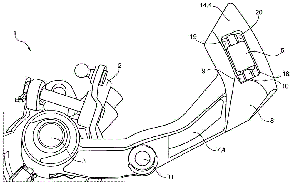
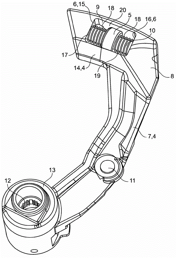
[0027] figure 1 A part of a shifting device 1 for an automotive gear transmission is shown. The manual selector lever, not shown, acts on the additional mass 4 via a suitable linkage or shift fork via the ball joint 11 . As a result, the selector shaft 3 is twisted, which engages or disengages a selector gear of the transmission by means of a selector lever finger (not shown). The selector shaft 3 can be moved axially with the selector lever 2 without the additional mass being axially moved together.

[0028] The cylinder 13 is mounted on the shift shaft 3 in a rotationally fixed manner by means of the internal toothing 12 . The cylinder 13 has a substantially radially oriented overhang 7 which transitions at its radially outer end 8 into a tangentially oriented curved end piece 14 . The end piece 14 and the boom 7 are formed in one piece and together form the additional mass 4 . Due to the rotationally fixed connection to the selector shaft 3 , the rotational or pivoting ...


PUM


Abstract

The invention relates to a shifting device (1) for a multi-speed gearbox of a motor vehicle having a shifting shaft (3) and an additional mass (4) which is coupled to the shifting shaft (3) during the shifting operation. The shifting device (1) has a damper mass (5) which is arranged so as to be movable with respect to the shifting shaft (3) in order to damp oscillations. In addition, the invention relates to a method for damping oscillations in such shifting devices (1).

Description

technical field [0001] The invention relates to a shifting device for an automotive gear transmission, having a shifting shaft and an additional mass connected to the shifting shaft during the shifting process. Background technique [0002] A shifting device according to the classification is known, for example, from DE 19636506 A1. It is considered a disadvantage here that during the shifting process of the motor vehicle gear transmission, due to the rapid shifting process, force peaks sometimes occur which place a high load on the device. According to the solution described in the alleged document, therefore, an additional mass which can rotate about the axis of rotation is arranged on the cantilever. The cantilever is connected to the selector lever via a guide rod that operates the selector shaft. [0003] When shifting gears, that is to say when the selector lever is actuated to engage a gear, the boom and the additional mass move together with the boom, which counter...

Claims


Application Information

Patent Timeline
Patent Type & Authority Patents(China)
IPC IPC(8): F16H61/24
CPCF16H61/24F16H59/0208F16H2061/246
Inventor 马库斯·罗斯特阿诺尔德·特里斯勒甘特·希尔特
Owner SCHAEFFLER TECH AG & CO KG
Learn More