Capillary pressure regulator with stable pressure-regulating performance

A capillary pressure regulator technology, applied in the field of pressure regulators, can solve the problems of inconspicuous adjustment of outlet pressure, inapplicability of capillary level flow, unstable outlet pressure, etc., to increase the use range, facilitate installation and replacement, and export The effect of pressure stabilization

Active Publication Date: 2014-03-26
CHINA AGRI UNIV
View PDF8 Cites 0 Cited by
  • Summary
  • Abstract
  • Description
  • Claims
  • Application Information

AI Technical Summary

Problems solved by technology

but, Figure 8 The water inlet direction of the inlet flower basket of the pressure regulator shown is the same as the main water flow direction. When the inlet pressure changes, the movement of the pressure regulating component 2 is not sensitive to the adjustment of the water head loss at the inlet flower basket, resulting in the adjustment of the outlet pressure is not obvious, making Its starting pressure is high (generally greater than 15m), and the outlet pressure is unstable
Secondly, Figure 8 The adjustable flow range of the branch pressure regulator shown is generally greater than 5m 3 / h, so it is not suitable for capillary flow (less than 1.5m 3 / h)
Again, capillary pressure regulators are still rare in my country

Method used


Image

  • Capillary pressure regulator with stable pressure-regulating performance
  • Capillary pressure regulator with stable pressure-regulating performance
  • Capillary pressure regulator with stable pressure-regulating performance

Examples


Embodiment 1

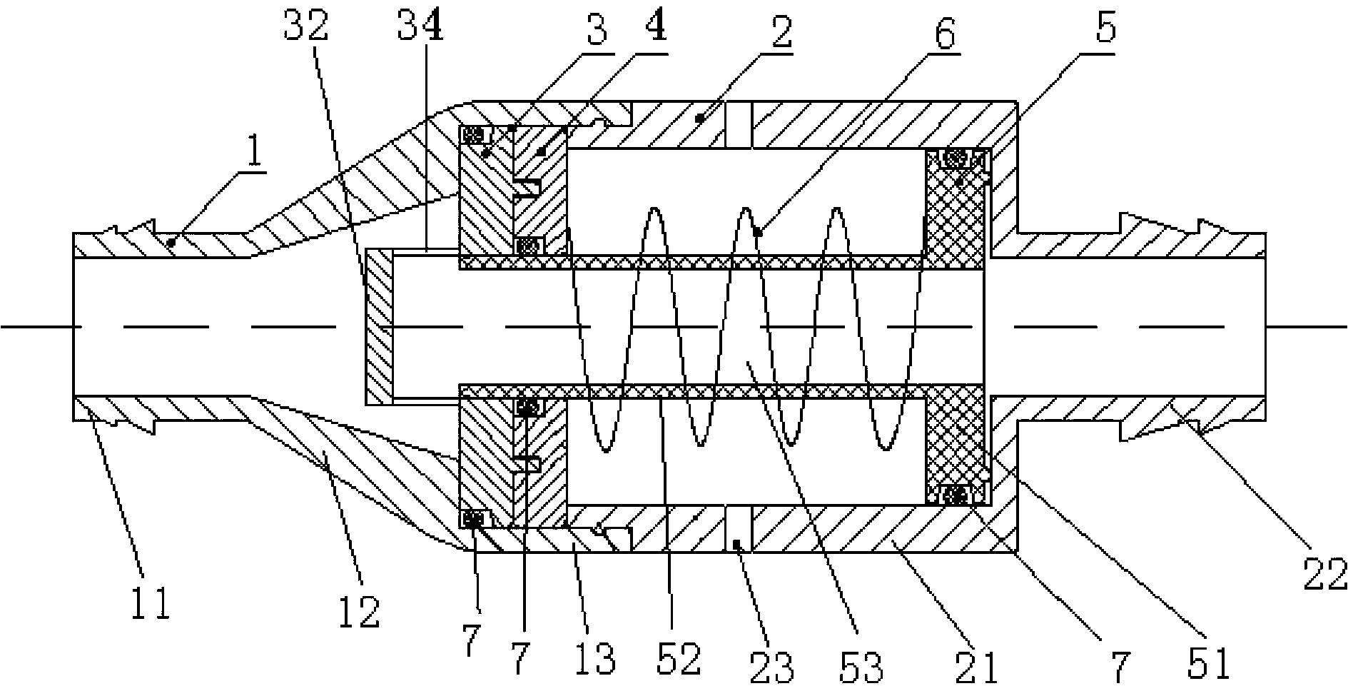
[0021] Such as figure 1 As shown, the present invention includes an upstream housing 1 , a downstream housing 2 , a guide body 3 , a pin support 4 , a T-shaped pressure regulating assembly 5 and a pressure regulating spring 6 .

[0022] Such as figure 1As shown, the upstream casing 1 of the present invention includes a first cylindrical section 11, a conical diffuser section 12 and a second cylindrical section 13 that are integrally arranged in sequence, and the central axis of the first cylindrical section 11 is the same as the central axis of the conical diffuser section 12 and the second cylindrical section. The central axes of the cylinder segments 13 coincide. The outer diameter of the first cylindrical section 11 is smaller than that of the second cylindrical section 13 , and the outer diameter of the conical diffuser section 12 gradually increases from the connection with the first cylindrical section 11 to the connection with the second cylindrical section 13 . The...

Embodiment 2

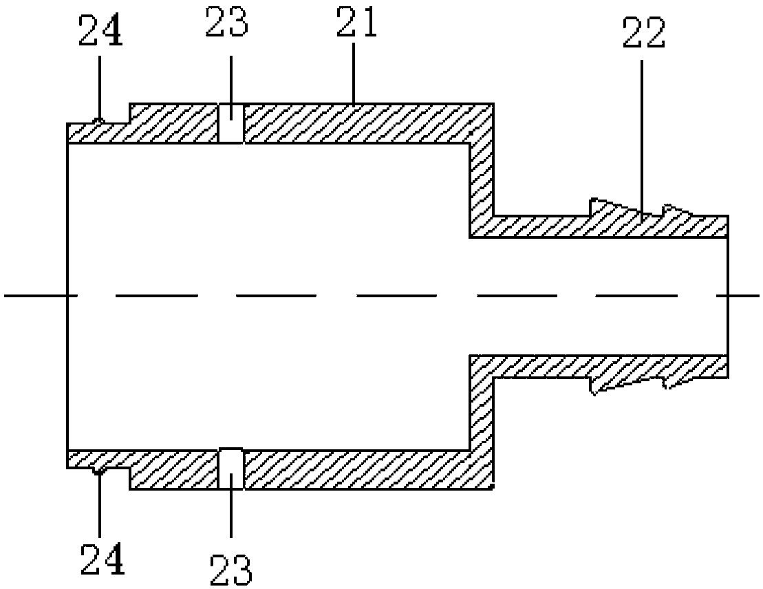
[0033] Such as Figure 7 As shown, the difference between the second embodiment and the first embodiment is that the downstream casing 2 of the present invention includes a third cylindrical section 21 and a fourth cylindrical section 22 integrally arranged, and the central axis of the third cylindrical section 21 is connected to the fourth cylindrical section. The central axis of the section 22 is vertical; that is, the side wall of the fourth cylindrical section 22 is provided with a through hole communicating with the inside of the third cylindrical section 21, and the diameter of the second circular body 51 of the T-shaped pressure regulating assembly 5 is larger than that of the fourth cylindrical section 22. The diameter of the through hole provided on the side wall of the cylindrical section 22 . Both ends of the fourth cylindrical section 22 are water outlets, and the end of the first cylindrical section 11 of the upstream casing 1 is a water inlet. The structure and ...


PUM


Abstract

The invention relates to a capillary pressure regulator with stable pressure-regulating performance. The capillary pressure regulator is characterized by comprising an upstream shell, a downstream shell, a baffle, a flat support, a T-shaped pressure-regulating component and a pressure-regulating spring, wherein the upstream shell comprises a first cylindrical section, a conical diffusion section and a second cylindrical section which are sequentially and integrally arranged; the downstream shell comprises a third cylindrical section and a fourth cylindrical section which are integrally arranged; the third cylindrical section is connected with the second cylindrical section; a plurality of gas ports are formed in the circumferential direction of the third cylindrical section at intervals; the baffle comprises a first rounded body and a cylindrical structure; the middle of the first rounded body is provided with a through cylindrical structure and an impermeable central hole; a plurality of water inlet holes which are communicated with the central hole are formed in the circumferential direction of the cylindrical structure; the first rounded body is arranged in the second cylindrical section; the cylindrical structure stretches into the conical diffusion section; the flat support is arranged in the second cylindrical section; the middle of the flat support is provided with a round hole of which the diameter is the same as that of the central hole of the baffle; the T-shaped pressure-regulating component comprises a second rounded body and a cylinder; the cylinder penetrates through the round hole on the flat tray and the central hole on the first rounded hole; and the pressure-regulating spring is sleeved on the cylinder of the T-shaped pressure-regulating component.

Description

technical field [0001] The invention relates to a pressure regulator in the field of agricultural water-saving irrigation, in particular to a capillary pressure regulator with stable pressure regulating performance. Background technique [0002] The pressure regulator is a device that regulates the pressure in the pipeline in the pressure pipeline irrigation system, and is an important part of the drip irrigation system. Irrigation uniformity is an important factor affecting the performance of the drip irrigation system. However, due to the different distances between the pipeline and the head of the system and the undulations of the terrain, the inlet pressure of different branch pipe inlets and different capillary inlets varies greatly, which leads to field drippers. The water flow is uneven. [0003] In order to effectively control the irrigation uniformity of the drip irrigation system, the existing main technical solutions are pressure regulation and flow regulation. ...

Claims


Application Information

Patent Timeline
Patent Type & Authority Patents(China)
IPC IPC(8): A01G25/02
Inventor 李光永齐成红
Owner CHINA AGRI UNIV
Why Eureka
Try Eureka