Friction stir welding member

A technology of friction stirring and joining parts, which is applied to welding equipment, welding/welding/cutting items, non-electric welding equipment, etc., can solve the problems of increased man-hours, etc., to prevent corrosion, reduce man-hours, and reduce operating man-hours Effect

Active Publication Date: 2013-04-10
HONDA MOTOR CO LTD
View PDF7 Cites 5 Cited by
  • Summary
  • Abstract
  • Description
  • Claims
  • Application Information

AI Technical Summary

Problems solved by technology

However, since the hole filling work described above is another work performed after the pin 204 is pulled out, the number of man-hours increases.

Method used


Image

  • Friction stir welding member
  • Friction stir welding member
  • Friction stir welding member

Examples


Embodiment

[0039] Embodiments of the present invention will be described with reference to the drawings.

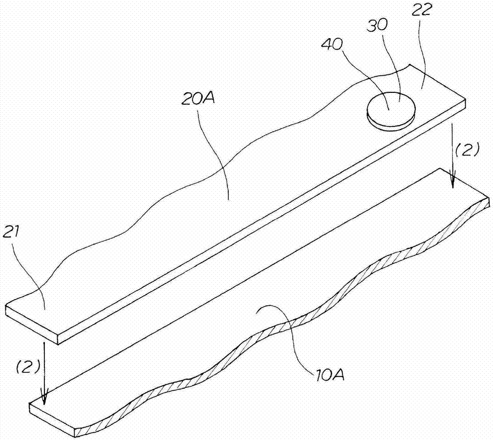
[0040] Such as figure 1 As shown, the second member 20A is stacked on the first member 10A arranged on the lower side as indicated by the arrow ( 2 ), and the second member 20A is positioned relative to the first member 10A. The second member 20A is a member having a material different from that of the first member 10A. Next, pass figure 2 The cross-sectional structures of the first member 10A and the second member 20A will be described.

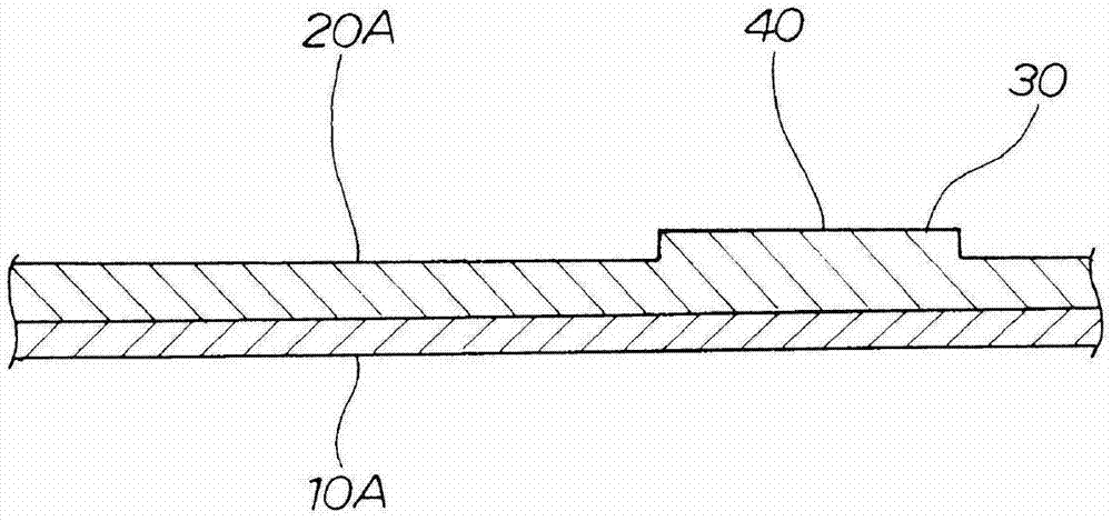
[0041] Such as figure 2 As shown, the second member 20A is integrally provided with a columnar second protrusion 30 protruding toward the bonding tool (described later) side. The second protrusion 30 is formed to be higher than the length (described later) of a pin (described later) of the bonding tool.

[0042] In addition, a joining end portion 40 (details will be described later) is provided on the second convex portion 30 . from one end...


PUM


Abstract

Tthe second projection 30 projecting toward the welding tool 50 is provided integrally with the second member 20A, and a height H1 of the second projection 30 is larger than a length h1 of the pin 51 of the welding tool 50. The second projection 30 is provided with the welding terminal portion 40, and the pin 51 is pulled out at the welding terminal portion 40 before the pin 51 reaches the other end of the second member 20A. When the pin 51 is pulled out at the welding terminal portion 40 at the end of welding and the welding terminal portion 40 solidifies, as illustrated in FIG. 3D, the pin-removed depression 61 having a volume corresponding to the volume of the pin 51 is formed in the second member 20A. Because a depth h2 of the pin-removed depression 61 is smaller than the height H1 of the second projection 30, the second member 20A has a remaining thickness t1 which is obtained by subtracting the depth h2 of the pin-removed depression 61 from the height H1 of the second projection 30. In order to have the remaining thickness t1 of the second member 20A, the pin 51 is just pulled out from the welding terminal portion 40 at the end of welding, and thus no additional work is necessary and the production time for the work is reduced.

Description

technical field [0001] The present invention relates to a friction stir welded member in which a second member is joined to the first member by a friction stir welding method in which a second member having a material different from that of the first member is laminated on the first member. Background technique [0002] As one of techniques for joining steel plates and aluminum plates, friction stir welding is known (for example, refer to Patent Document 1( figure 2 )). [0003] Patent Document 1 is explained based on the following figure. [0004] Figure 15 This is a diagram illustrating the basic principle of conventional technology. In the friction stir welding method, a second member 202 made of a material different from that of the first member 201 is stacked on a first member 201 , and a joining tool rotated as indicated by the arrow (1) The pin 204 of 203 is inserted into this second part 202 . The bonding tool 203 is relatively moved while the tip of the pin 204...

Claims


Application Information

Patent Timeline
Patent Type & Authority Applications(China)
IPC IPC(8): B23K20/12
CPCB23K20/12B23K2201/18B23K20/1265B23K2203/20B23K20/122B23K20/1225B23K2101/18B23K2103/20Y10T428/24612
Inventor 佐山满小林努宫原哲也大浜彰介
Owner HONDA MOTOR CO LTD
Why Eureka
Try Eureka