Subway platform screen door panel lock

A technology for subways and facades, applied in building locks, buildings, building structures, etc., can solve problems such as affecting operation, easy upturning of the panel 100, and inability to lock smoothly, meeting the requirements of cleanliness, and not easily deformed and upturned. Effect

Active Publication Date: 2014-11-12
PANASONIC MFG BEIJING
View PDF4 Cites 0 Cited by
  • Summary
  • Abstract
  • Description
  • Claims
  • Application Information

AI Technical Summary

Problems solved by technology

Although this kind of locking mechanism has a simple structure, it requires relatively high installation accuracy of the lock. If there is a slight difference in the mechanical cooperation position between each other, it is likely to cause failure to lock smoothly and affect the operation.
At the same time, when closing the panel, one hand needs to press and close the panel 100, and the other hand turns the key to lock it manually, which virtually increases a lot of inconvenience in operation.
In addition, this structure makes the distance between the panel 100 and the fixed structure unadjustable, and it is not convenient for the operator to adjust the installation position of the panel 100 and the fixed structure during actual installation and construction.
Finally, since the lock 300 in the prior art is arranged in the middle of the lower side of the panel 100, the locking position between the panel 100 and the fixed structure is located in the middle of the panel 100, so that the two ends of the panel 100 are easy to be upturned, and the connection between the fixed structure and the panel 100 is easy. A large gap is formed between them, which cannot meet the requirements of the internal cleanliness of the fixed structure.

Method used


Image

  • Subway platform screen door panel lock
  • Subway platform screen door panel lock
  • Subway platform screen door panel lock

Examples


Embodiment Construction

[0038] The subway screen door panel lock according to the embodiment of the present invention will be further described in detail below in conjunction with the accompanying drawings and specific embodiments, but it is not intended to limit the present invention.

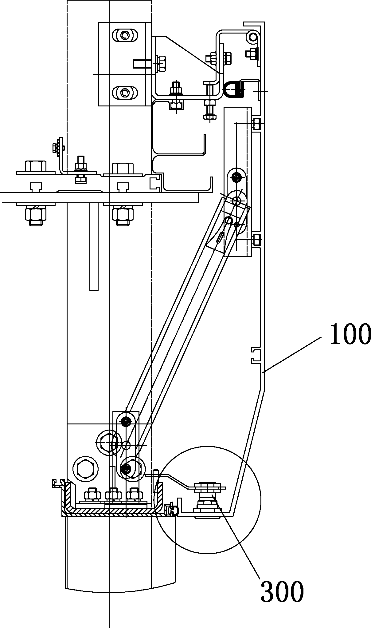
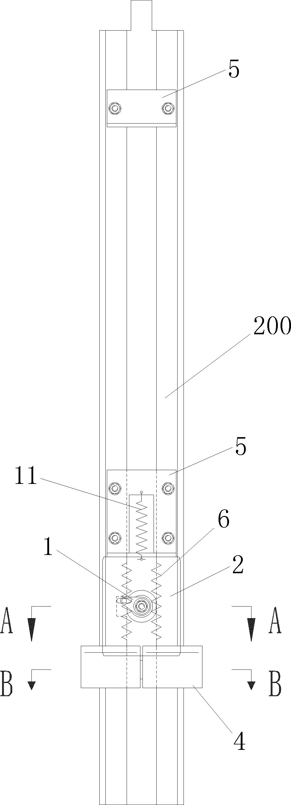
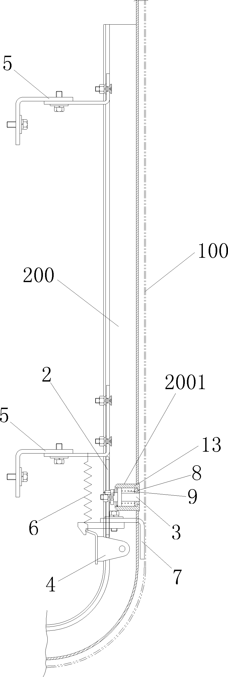
[0039] figure 2 In order to show the front structure diagram of the subway screen door panel lock installed on the total support and the panel of the embodiment of the present invention, image 3 For showing the embodiment of the present invention, the panel lock of the subway screen door is installed on the side sectional structural schematic diagram of the total support and the panel, Figure 4 It is a schematic diagram of the cooperation structure of the lock cylinder assembly and the slide plate of the subway screen door panel lock according to the embodiment of the present invention, Figure 5 In order to show the schematic diagram of the interlocking structure of the locking mechanism and the locking mechanis...


PUM


Abstract

The invention discloses a subway platform screen door panel lock, which is used for locking a master support and a panel which covers the external side of the master support. At least one end of the master support is exposed out of the panel. The subway platform screen door panel lock comprises a plug assembly, a locking mechanism which is connected onto the master support, and a clamping mechanism with one end being connected with the panel and the other end being clamped with the locking mechanism. The end of the master support which is exposed out of the panel is provided with a plug slot. The plug assembly is embedded in the plug slot. One end of a lock rod is fixedly connected with a rotating driving sheet. During rotation of the lock rod, the rotating driving sheet drives a sliding plate to move from an initial position and push the locking mechanism to leave a position where the locking mechanism and the clamping mechanism are mutually clamped, the panel is opened, the sliding plate is restored to the initial position and the locking mechanism is automatically restored to the clamped position; and when the panel is fastened towards the master support, the panel drives the clamping mechanism to get close to the locking mechanism and enable the other end of the clamping mechanism to be clamped with the locking mechanism. By using the subway platform screen door panel lock, automatic locking can be realized when the panel and the master support are fastened.

Description

technical field [0001] The invention relates to a panel lock, in particular to a panel lock for a subway screen door. Background technique [0002] figure 1 It is a structural schematic diagram of a subway screen door panel lock in the prior art. Such as figure 1 As shown, the interlocking between the panel 100 and the fixed structure in the prior art is realized by a lock 300 installed on the lower side of the panel 100 . When locking, turn the lock 300 with a key to lock the lock 300 with the corresponding locking part on the fixed structure. When unlocking, turn the lock 300 with the key to disengage from the corresponding locking part on the fixed structure. Although this kind of locking mechanism has a simple structure, it requires relatively high installation precision of the lock. If there is a slight difference in the mechanical cooperation position between each other, it may cause failure to lock smoothly and affect the operation. At the same time, when closing ...

Claims


Application Information

Patent Timeline
Patent Type & Authority Patents(China)
IPC IPC(8): E05B65/48E05B63/06E05B17/22E05B17/18
Inventor 汪文志余和军郭峰
Owner PANASONIC MFG BEIJING
Why Eureka
Try Eureka