Refrigerant pump

A refrigerant pump and refrigerant technology, applied to pumps, pump components, pump devices, etc., can solve problems such as conflicts and energy consumption, and achieve the effects of reducing eddy current loss, reducing separation loss, and improving efficiency

Inactive Publication Date: 2013-04-10
XI AN JIAOTONG UNIV +1
View PDF7 Cites 4 Cited by
  • Summary
  • Abstract
  • Description
  • Claims
  • Application Information

AI Technical Summary

Problems solved by technology

[0005] However, when a disc-shaped impeller is formed with a plurality of through-holes (blade grooves), the radially outer sides of the blade grooves or through-holes are covered by the outer circumfer

Method used


Image

  • Refrigerant pump
  • Refrigerant pump
  • Refrigerant pump

Examples


Embodiment Construction

[0054] The present invention will be further described in detail below in conjunction with specific embodiments, which are explanations of the present invention rather than limitations.

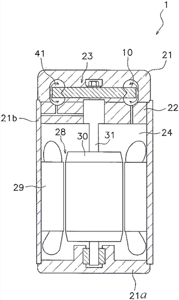
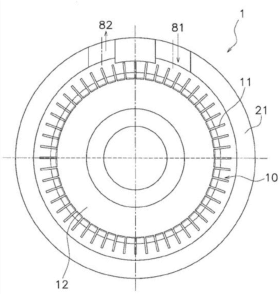
[0055] The refrigerant pump provided by the invention reduces the energy loss when the impeller rotates and improves the efficiency of the refrigerant pump by improving the blade of the impeller and the shape of the flow channel between the impeller and the shell. The refrigerant pump can be used for the refrigerant cycle of refrigeration devices and air-conditioning devices.

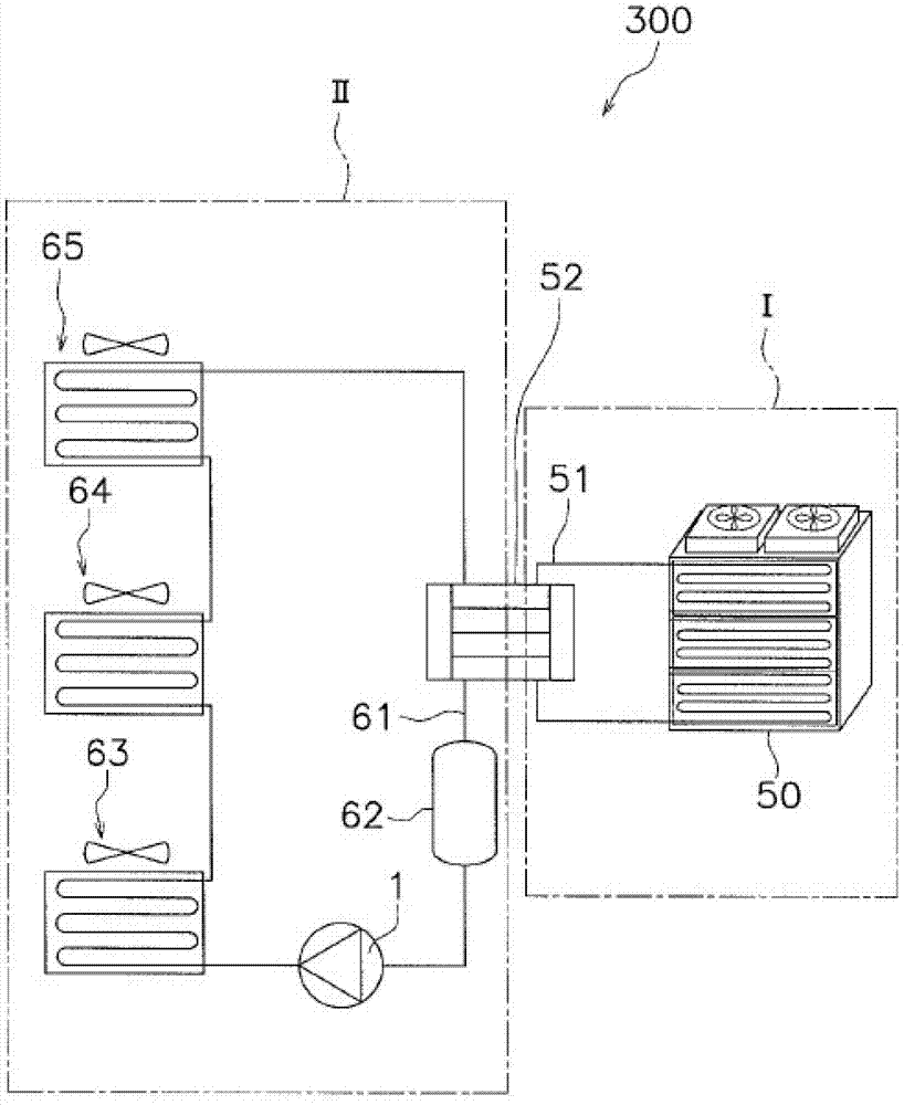
[0056] Specifically, the refrigerant pump is used in an air conditioner for illustration. see figure 1 The refrigerant piping system diagram of the air-conditioning apparatus 300 shown. The air conditioner 300 is composed of a heat source side refrigerant circuit I and a utilization side refrigerant circuit II. Refrigerant I in the heat source side refrigerant circuit I and refrigerant II in the utilization side refr...


PUM


Abstract

The invention discloses a refrigerant pump, which comprises a shell, wherein the interior of the shell is partitioned into a rotor chamber and a motor chamber by a dividing plate, an impeller is arranged in the rotor chamber, and a refrigerant main runner is formed between the rotor chamber and the impeller; and the rotor chamber is also provided with a suction inlet and an exhaust outlet which cover the side part and the radial outer side of the impeller. The shape of the shell which is in contact with fluid is approximately identical with the eddy direction, so that the eddy loss is reduced; and in addition, the separating loss of the fluid flowing at an inlet of the impeller is reduced, and the flowing property of the fluid is improved. On the basis that the shapes of blades incline towards the rotating direction, the runner between the side surfaces of the blades and the shell component is semicircular, so that the impeller efficiency can be further improved, and the whole efficiency of the pump can be further improved.

Description

technical field [0001] The invention belongs to the technical field of fluid machinery, in particular to a refrigerant pump. Background technique [0002] Refrigerant pumps, which are fluid machines that circulate refrigerant, are provided in refrigerant piping used in refrigerators and air conditioners. In the refrigerant pump disclosed in Patent Document 1 (JP 2003-161284 ), an impeller having a plurality of blades arranged on the outer edge is arranged in a housing having a fluid suction port and a discharge port and forming an annular flow path. The impeller rotates at a high speed in the shell, so that the refrigerant rotates roughly one circle to obtain the refrigerant with the required lift. [0003] However, the blades of this refrigerant pump are in the shape of a flat plate, and when the impeller rotates, a large separation loss occurs at the inlet of the impeller. Furthermore, in the refrigerant pump disclosed in Patent Document 1, since the cross-sectional shap...

Claims


Application Information

Patent Timeline
IPC IPC(8): F04D13/06F04D29/22F04D29/24
Inventor 张楚华刘思杨洋古庄和宏
Owner XI AN JIAOTONG UNIV
Why Eureka
Try Eureka