Pile fabric transfer printing device

A transfer printing, plush fabric technology, applied in transfer printing, rotary printing machine, transfer local treatment and other directions, can solve the problem of non-vertical wool on the cloth, and achieve the effect of improving the effect of the cloth.

Inactive Publication Date: 2013-04-17
夏美顺
View PDF6 Cites 3 Cited by
  • Summary
  • Abstract
  • Description
  • Claims
  • Application Information

AI Technical Summary

Problems solved by technology

[0003] The purpose of the present invention is to overcome the deficiencies in the prior art, to provide a plush fabric transfer printing device, which solves the problem that the plush fabric is not vertical after transfer printing

Method used


Image

  • Pile fabric transfer printing device

Examples


Embodiment Construction

[0013] The present invention will be further described below in conjunction with specific drawings.

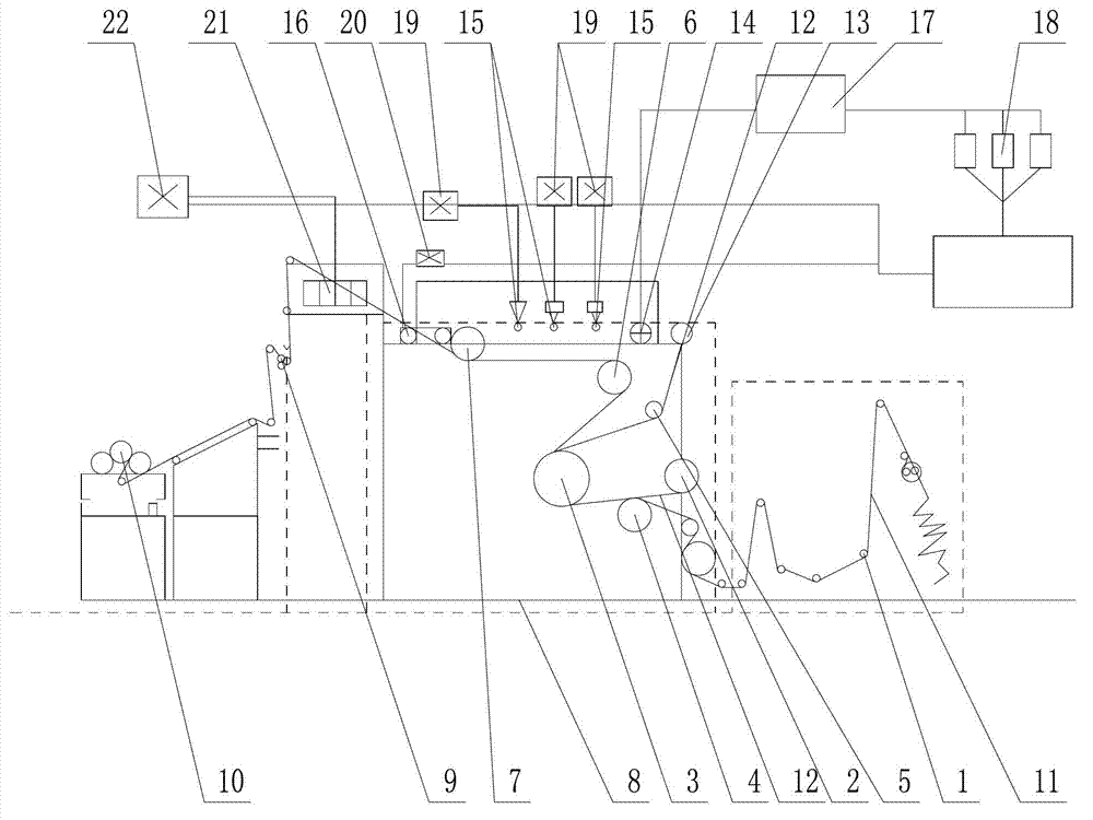
[0014] Such as figure 1 As shown: the plush fabric transfer printing device includes a cloth feed roller 1, a paper feed roller 2, a heating roller 3, an input roller 4, a paper discharge roller 5, a first cloth discharge roller 6, a second cloth discharge roller 7, a printing roller Chamber 8, Cloth Receiving Roller 9, Roller 10, Fabric 11, Printing Paper 12, Paper Receiving Roller 13, Vacuum Port 14, High Pressure Vent 15, Water Cooling Vent 16, Air Bag 17, Air Compressor 18, High Pressure Fan 19 , water-cooled motor 20, cooling tuyere 21, cooling fan 22, etc.

[0015] Such as figure 1 As shown, the present invention includes a cloth feeding mechanism, a printing mechanism and a winding mechanism, and the cloth feeding mechanism includes several cloth feeding rollers 1 for inputting fabric 11, and the rear side of the cloth feeding roller 1 is provided for inputting printi...


PUM


Abstract

The invention relates to a pile fabric transfer printing device which includes a cloth feeding mechanism, a printing mechanism and a winding mechanism. The printing mechanism includes a printing chamber in which a heating roller is arranged, a feeding roller is arranged along a cloth feeding direction of the heating roller and a paper delivery roller, a first draw-out roller and a second draw-out roller are arranged along a cloth draw-out direction of the heating roller. The fabrics are windingly arranged on a plurality of cloth feeding rollers, the feeding roller, the heating roller, the first draw-out roller, the second draw-out roller and the winding mechanism in sequence. Printing paper is wound round the feeding roller through a paper feeding roller, printing paper and the fabrics are wound around the heating roller together, and the printing paper is wound around a paper collecting roller through the paper delivery roller. The pile fabric transfer printing device is characterized in that a vacuum pile absorbing device is arranged on the upper portion of the printing chamber and the vacuum pile absorbing device includes vacuum pumping port, a plurality of high pressure tuyeres and water-cooling tuyeres which are arranged in sequence along a direction from the first draw-out roller to the second draw-out roller. The pile fabric transfer printing device solves the problem that piles of a cloth surface are not upright after a pile fabric is subjected to transfer printing and improves cloth surface effects after a pile fabric is subjected to transfer printing.

Description

technical field [0001] The invention relates to a printing device, in particular to a plush fabric transfer printing device. Background technique [0002] Transfer printing is a printing method that first prints dyes on other materials such as paper, and then uses hot pressing to transfer the pattern to the fabric. It is mostly used for printing chemical fiber knitwear and clothing. Transfer printing is generally carried out with a transfer printing machine. When the transfer printing paper and the fabric pass between the two pressure rollers in a close shape, the pattern printed by the dye on the transfer printing paper will be sublimated and transferred to the surface under the action of pressure and temperature. on the fabric. In the prior art, the defect that exists when the plush fabric is transferred by transfer printing machine is: the wool on the surface of the plush fabric is not vertical after printing due to the pressure of the pressure roller, which affects the ...

Claims


Application Information

Patent Timeline
Patent Type & Authority Applications(China)
IPC IPC(8): B41F16/02
CPCD06B11/0076
Inventor 夏美顺
Owner 夏美顺
Why Eureka
Try Eureka