Angle driver and steering control mechanism

An angular transmission and meshing mechanism technology, applied in mechanical steering gears and other directions, can solve the problems of excessive steering four-bar linkage, abnormal tire wear, increased clearance and other problems, so as to overcome the difficulty of layout and the adjustment of assembly and coordination. Convenience and stiffness-enhancing effect

Active Publication Date: 2013-04-17
XUZHOU HEAVY MASCH CO LTD
View PDF9 Cites 4 Cited by
  • Summary
  • Abstract
  • Description
  • Claims
  • Application Information

AI Technical Summary

Problems solved by technology

The disadvantage of this steering mechanism is: there are too many steering four-bar linkages; the transmission of force and the transfer of steering motion need to be determined according to the specific stiffness of the steering system. The greater the stiffness of the steering system, the faster the transmission of force, and the rear axle turns It is also fast; after a period of use, the ball studs at both ends of the steering rod assembly will wear out, the gap will increase, and the lag of the rear axle steering will increase, which will also cause abnormal wear of the tires to a certain extent
However, the angle transmission used therein has only one output and can only be connected to a mechanical power steering
[0010] If the existing above steering mechanism is applied to figure 1 and figure 2 In the multi-axle truck crane shown in , it is necessary to arrange multiple angle drives according to the position and number of the mechanical power steering gear and the hydraulic steering gear actually required. This arrangement is more difficult and the cost is higher

Method used


Image

  • Angle driver and steering control mechanism
  • Angle driver and steering control mechanism
  • Angle driver and steering control mechanism

Examples


Embodiment Construction

[0042] The technical solutions of the present invention will be described in further detail below with reference to the accompanying drawings and embodiments.

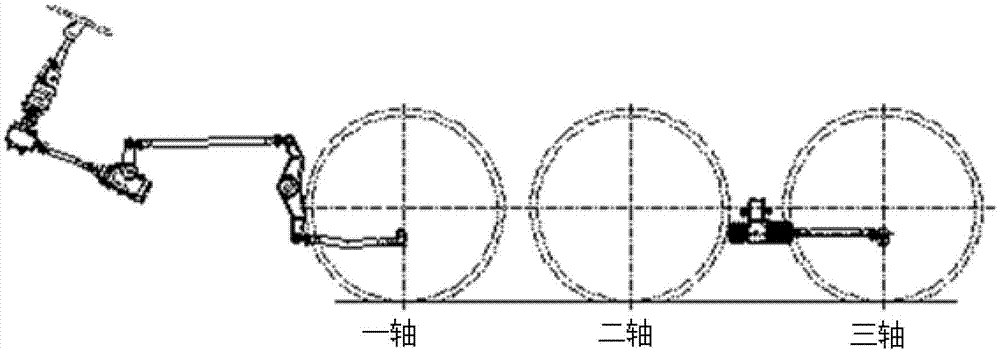
[0043] Figure 7 It is a schematic front view of an embodiment of the angular transmission provided by the present invention, Figure 4 for Figure 8 sectional schematic diagram. Such as Figure 7 , Figure 8 As shown, compared with the angle transmission in the prior art, the angle transmission 1 provided by the present invention includes an input shaft 2 , a first output shaft 3 , an engagement mechanism, a first housing 4 and a second housing 5 . Wherein: the axis of the input shaft 2 is perpendicular to the axis of the first output shaft 3 , and the input shaft 2 is rotationally connected with the first output shaft 3 through the engaging mechanism.

[0044] However, in view of the fact that the first output shaft 3 can only be connected to a steering gear, the angle transmission 1 provided by the present inve...


PUM


Abstract

The invention relates to an angle driver and a steering control mechanism. The angle driver comprises an input shaft, a first output shaft, a meshing mechanism, a first shell, a second shell and a second output shaft. The axis of the input shaft is perpendicular to that of the first output shaft, the input shaft is rotatably connected with the first output shaft through the meshing mechanism, the input shaft and the first output shaft are supported in the first shell and the second shell respectively through first bearings, the second output shaft and the input shaft are rigidly connected on the same straight line, the second output shaft is supported in the first shell through a second bearing, and an input end of the input shaft, an output end of the first output shaft and an output end of the second output shaft extend out of the shells. The angle driver can be simultaneously connected with a mechanical power steering gear and a hydraulic steering gear, and is low in cost.

Description

technical field [0001] The invention relates to an automobile steering device, in particular to an angle transmission and a steering mechanism provided with the angle transmission. Background technique [0002] In recent years, with the construction and maintenance of more and more large-scale wind power and other new energy projects, as well as the demand for large-scale petrochemical and power plant construction, the truck crane market has achieved considerable development. In order to meet the requirements of maneuvering flexibility and curve passing ability when the vehicle is transferred at a short-distance site or turning at a low speed, the truck cranes currently produced with telescopic booms or lattice booms generally have three or more axles. Most of them have at least one rear axle that can be actively steered or follow-up steering. [0003] For the convenience of description, a schematic diagram of the appearance of a three-axle all-terrain crane and a six-axle ...

Claims


Application Information

Patent Timeline
Patent Type & Authority Applications(China)
IPC IPC(8): B62D3/02
Inventor 王志芳曹培雷
Owner XUZHOU HEAVY MASCH CO LTD
Why Eureka
Try Eureka