
Steel floor

A steel and floor technology, applied in the direction of floors, buildings, building structures, etc., can solve the problems that hollow steel plates cannot withstand the heavy pressure of large equipment, and solid steel plates have defective anti-static effects, and achieve convenient installation and simple principles Effect

Inactive Publication Date: 2013-04-17
SHAANXI LONGHAI ENG CONSTR
View PDF0 Cites 0 Cited by
  • Summary
  • Abstract
  • Description
  • Claims
  • Application Information

AI Technical Summary

Problems solved by technology

[0003] In these cases, steel anti-static floors are generally necessary. Among the existing steel anti-static steel plates, the anti-static effect of solid steel plates has been proven to be defective, while hollow steel plates cannot withstand the heavy pressure of large equipment.

Method used


Image

  • Steel floor

Examples


Embodiment Construction

[0009] The present invention will be described in more detail below in conjunction with the accompanying drawings and embodiments.

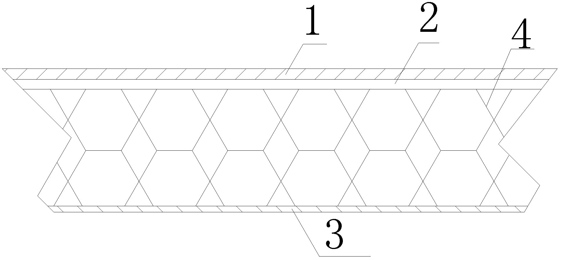
[0010] As shown in the figure, the present invention is a steel floor with an antistatic layer 2 on a steel base plate, characterized in that the steel base plate includes a top plate 2 and a bottom plate 3, and the top plate 2 and the bottom plate 3 are separated by a honeycomb Shaped support plate 4 connection.

[0011] The honeycomb-shaped structural feature can guarantee to support a large weight and effectively reduce the weight, and the static electricity of friction can be quickly transmitted to the ground through the support plate 4, so that the anti-static effect is better.

[0012] Compared with the prior art, the present invention can withstand heavy pressure while ensuring the antistatic effect, and has simple principle and convenient installation.


PUM


Abstract

The invention discloses a steel floor. An anti-static layer is arranged on a steel base plate. The steel floor is characterized by comprising a top plate and a base plate which are connected through a honeycombed support plate. The steel floor ensures static effect, simultaneously can bear great pressure, and is simple in theory and convenient to install.

Description

technical field [0001] The invention relates to the technical field of special equipment, in particular to a steel floor. Background technique [0002] At present, there are more and more large computer rooms and electronic equipment production workshops. In these places, static electricity has become the biggest enemy. How to prevent static electricity is a major problem facing these places. Generally speaking, in addition to human factors, environmental conditions are Most importantly, the ground, as the biggest source of frictional static electricity, is the top priority of protection. [0003] In these cases, steel anti-static floors are generally necessary. Among the existing steel anti-static steel plates, the anti-static effect of solid steel plates has been proven to be defective, and hollow steel plates cannot withstand the heavy pressure of large equipment. Contents of the invention [0004] In order to overcome the deficiencies of the above-mentioned prior art,...

Claims


Application Information

Patent Timeline
Patent Type & Authority Applications(China)
IPC IPC(8): E04F15/06
Inventor 刘清洁
Owner SHAANXI LONGHAI ENG CONSTR
Learn More