A led sensor light
A technology of LED induction lamp and lamp body, which is applied in lighting and heating equipment, semiconductor devices of light-emitting elements, point light sources, etc., can solve the problems of single structure and single function, and achieve the effect of easy adjustment and novel and unique design
- Summary
- Abstract
- Description
- Claims
- Application Information
AI Technical Summary
Problems solved by technology
Method used
Image
Examples
Embodiment 1
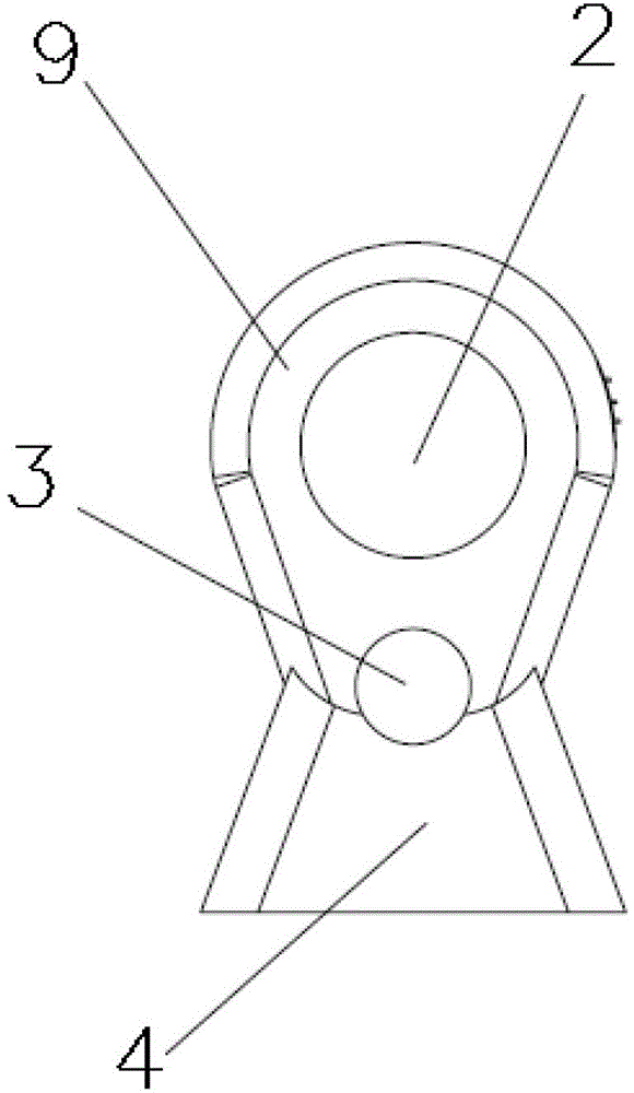
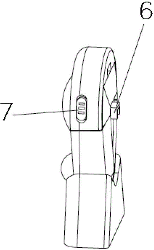
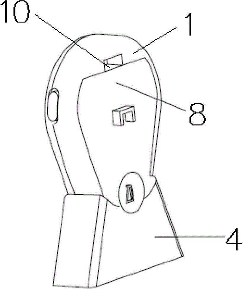
[0025] Such as Figure 1~6 As shown, an LED induction lamp includes a lamp body 1, a protective screen 2, an infrared sensor 3, a base 4, a simple bracket 5, a mounting buckle 6, a switch adjustment button 7, a back cover 8, a lamp cover 9, and a buckle 10. The lamp body 1 and the lamp cover 9 are both upper and lower arc transitions and the upper arc radius is greater than the lower arc radius. The front of the lamp body 1 is provided with a lamp cover 9, and the upper part of the lamp cover 9 is installed with a transparent protective screen 2. , The lower part of the front of the lamp cover 9 is equipped with an infrared sensor lens 3, and there is a switch adjustment button 7 on the side of the lamp cover 9. The switch adjustment button 7 is matched with the switch on the circuit board to realize the switch function of the lamp; the rear of the lamp body 1 is The back cover 8 has a mounting buckle 6 and a buckle 10 on the back cover 8. The arc edge of the lamp body 1 is pr...
Embodiment 2
[0028] Such as Figure 1~6 As shown, the shape of the simple support 5 is that one flat plate extends diagonally from another flat plate to form a chevron-shaped support. The plane of the support is provided with two sliding grooves and fixing holes. The chevron-shaped support has two It is composed of components. Each end of the two components is connected by a hinge, and the other end is connected with the plane of the bracket. One end of one component is connected with the sliding groove to form a sliding movement, and one end of the other component is connected with one end of the flat plate to form a herringbone. The other plate is provided with a boss, which is matched with the mounting buckle 6 on the back cover 8 and the mounting buckle 6 on the back cover is matched. Fix or paste the simple bracket 5 on the wall, and then fit the mounting buckle 6 of the back cover 8 to the boss of the bracket.
PUM
 Abstract
Description
Claims
Application Information
 - R&D
- Intellectual Property
- Life Sciences
- Materials
- Tech Scout
- Unparalleled Data Quality
- Higher Quality Content
- 60% Fewer Hallucinations
Browse by: Latest US Patents, China's latest patents, Technical Efficacy Thesaurus, Application Domain, Technology Topic, Popular Technical Reports.
© 2025 PatSnap. All rights reserved.Legal|Privacy policy|Modern Slavery Act Transparency Statement|Sitemap|About US| Contact US: help@patsnap.com


