Measuring device for dynamic position of rear beam

A measuring device and dynamic position technology, applied in the direction of measuring devices, optical devices, instruments, etc., can solve problems such as irregularity and difficult measurement, and achieve the effect of increasing the detection distance

Active Publication Date: 2015-10-28
WUJIANG WANGONG ELECTROMECHANICAL EQUIP
View PDF4 Cites 0 Cited by
  • Summary
  • Abstract
  • Description
  • Claims
  • Application Information

AI Technical Summary

Problems solved by technology

The back beam moves with the height of the opening, the position of the back beam is not only high or low, but also front and back, and irregular, so it is difficult to measure

Method used


Image

  • Measuring device for dynamic position of rear beam
  • Measuring device for dynamic position of rear beam
  • Measuring device for dynamic position of rear beam

Examples


Embodiment Construction

[0026] The present invention will be described in detail below with reference to the accompanying drawings and in combination with embodiments.

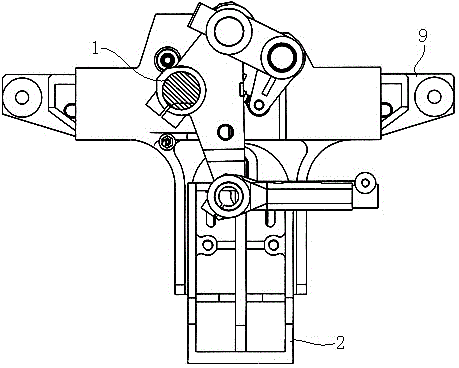
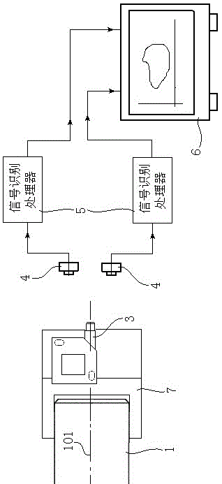
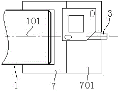
[0027] refer to Figure 1 to Figure 5 As shown, a dynamic position measuring device for the back rest includes a light emitting tube 3 connected to the back rest 1 and a pair of light receivers 4 that are stationary relative to the frame 2 . The light emitting tube 3 is connected to the back beam 1 through a connecting seat 7, one end of the connecting seat 7 is sleeved on the end of the back beam 1, and the other end has a radially arranged installation groove 701, and the light emitting tube 3 can be The position and direction are adjusted in the installation groove 701 and fixed by bolts, and the connecting seat 7 is placed outside the frame 2 . The pair of optical receivers 4 are fixed on the T-shaped arm 9 through the detection frame 8 , the T-shaped arm 9 is fixed on the frame 2 , and the detection frame 8 is placed outside th...


PUM


Abstract

The invention discloses a dynamic position measuring device of a back beam. The dynamic position measuring device comprise a light emission tube and a pair of light receivers, wherein the light emission tube is connected with the back beam, and the pair of light receivers is static relative to a stand; the emission direction extension cord of the light emission tube is superposed with an axial line of the back beam, and a plane in which the receiving ends of the two light receivers are located is parallel to the end surface of the back beam; and signals received by the light receivers are sequentially transmitted to a signal identification processor and a computer, and the computer computes the position of the back beam through analysis software and a time window. According to the dynamic position measuring device of the back beam, disclosed by the invention, the positions of the back beam at each stage from a starting position, a regular operating position and a stopping position of a weaving machine are monitored so that parameters of the weaving machine are conveniently and immediately adjusted, fabric obtains optimal fabric average rate and a minimum of woven defects, the bearing capacity of warp is improved and the operation speed of the weaving machine is increased.

Description

technical field [0001] The invention relates to a measuring device in the field of looms, in particular to a measuring device for the dynamic position of a back rest. Background technique [0002] Among the many movements of the loom, the movement of the backrest is the most complex. The back beam moves with the height of the opening. The position of the back beam is not only high or low, but also front and back, and irregular, so it is difficult to measure. The movement of the back beam is related to factors such as the height of the shed, the let-off amount of the let-off motor, the type of warp yarn, the tension of the warp yarn, the tension of the fabric, and the position of the weaving fell. Therefore, it is very important to measure the position of the backrest at each stage from the starting position of the loom to normal operation to the stop position of the loom. The movement of the backrest directly affects the quality of the fabric, the bearing capacity of the wa...

Claims


Application Information

Patent Timeline
Patent Type & Authority Patents(China)
IPC IPC(8): G01B11/00
Inventor 周平祝章琛
Owner WUJIANG WANGONG ELECTROMECHANICAL EQUIP
Why Eureka
Try Eureka