
Low-oscillation dispersion mirror structure and design method thereof

A dispersive mirror and low-dispersion technology, applied in the field of low-oscillation dispersive mirror structure, can solve the problems of large design engineering and high manufacturing cost

Active Publication Date: 2017-05-17
SHANGHAI INST OF OPTICS & FINE MECHANICS CHINESE ACAD OF SCI
View PDF2 Cites 14 Cited by
  • Summary
  • Abstract
  • Description
  • Claims
  • Application Information

AI Technical Summary

Problems solved by technology

[0003] Dispersion mirror pair is currently the most common dispersion compensation element in commercial use. The dispersion mirror pair is used by changing the reference wavelength of the dispersion mirror or using it under different incident angles, so that the oscillation period of one of the dispersion mirrors is shifted by half a period, so that the two The positive and negative values ​​of the ripples of the mirrors cancel each other out. Although the oscillation ripples of each mirror are large, the group delay dispersion curve is relatively smooth when the two mirrors are used together.
However, since the dispersive mirror pairs need to be designed and manufactured in pairs, not only the amount of design engineering is large, but also the manufacturing cost is relatively high.

Method used


Image

  • Low-oscillation dispersion mirror structure and design method thereof
  • Low-oscillation dispersion mirror structure and design method thereof
  • Low-oscillation dispersion mirror structure and design method thereof

Examples


Embodiment 1

[0031] The low oscillation dispersion mirror index required by Embodiment 1 is: group delay dispersion value -200fs 2 , Reflectivity > 99.8%, corresponding bandwidth is 800nm ​​central wavelength 200nm bandwidth.

[0032] The design steps are as follows:

[0033] 1. According to the group delay dispersion and bandwidth requirements, the amount of dispersion is relatively large and the bandwidth is wide, so the high refractive index material Nb with a high refractive index is selected 2 o 5 , the low refractive index material is SiO 2 , the refractive index parameters of high and low refractive index materials are given by the Cauchy formula Sure.

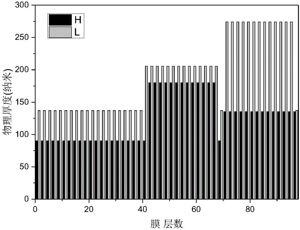
[0034] 2. According to the requirements of the low-oscillation dispersion mirror, select appropriate parameters and substitute them into the film structure expression G / (HL)^n(HL)^m(HxLH)^k(LxHL)^kM / A of the low-oscillation dispersion mirror, The film structure is obtained as figure 2 mentioned.

[0035]3. Based on the init...


PUM


Abstract

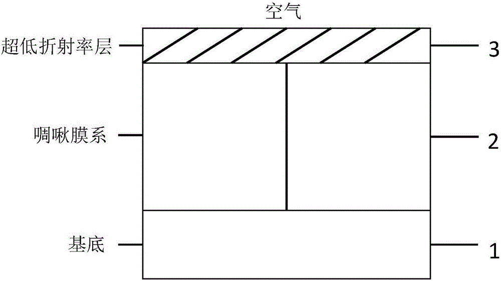
The invention discloses a design for a low-oscillation dispersion mirror structure. The structure comprises a substrate, a chirped film system structure and an ultralow-refractive-index layer. The structure is characterized in that the ultralow-refractive-index layer is additionally arranged on the top part of the chirped film system structure and is realized by an inclined deposition technology, the refractive index and thickness of the ultralow-refractive-index layer can be controlled by adjusting the rate and angle of inclined deposition, and the refractive index of the chirped film system structure can be well matched with an air layer, so that the dispersion oscillation can be greatly reduced. Due to the designed structure, the dispersion oscillations of dispersion mirrors with different bandwidths and dispersion amounts can be greatly reduced, and the dispersion mirror design needs for low loss, low oscillation and large dispersion compensation amount for pulse compression in an ultrafast laser system are well met. The low-oscillation dispersion mirror structure can be applied in the ultrafast laser system (such as a chirped pulse amplification technology and an optical-fiber laser), and is an essential dispersion compensation element in the ultrafast laser system.

Description

technical field [0001] The invention belongs to the field of ultrafast lasers, in particular to a super-low refractive index obliquely deposited SiO on the surface of an ultrashort pulse laser used for pulse compression optical elements 2 layered low-oscillation dispersion mirror structure. Background technique [0002] Dispersion mirror is a kind of dispersion compensating element, which can provide certain dispersion compensation while maintaining high reflectivity. It can replace prism pair and grating in ultrafast laser system for pulse compression. Dispersion mirrors are divided into high dispersion mirrors, low dispersion mirrors and broadband chirped mirrors. When the bandwidth of the dispersive mirror increases or the amount of dispersion increases, relatively large dispersion oscillations may be introduced. This is because in the structure of the dispersive mirror, there is a serious impedance mismatch between the chirped film system and the external medium (mainl...

Claims


Application Information

Patent Timeline
Patent Type & Authority Applications(China)
IPC IPC(8): G02B5/00G02B1/10
CPCG02B1/10G02B5/00
Inventor 王胭脂刘加陈宇郭可升朱晔新王涛朱美萍张伟丽王建国赵娇玲孙建齐红基易葵邵建达
Owner SHANGHAI INST OF OPTICS & FINE MECHANICS CHINESE ACAD OF SCI
Learn More