Chb cascaded photovoltaic inverter circuit based on three-phase multi-split transformer

A photovoltaic inverter and multi-splitting technology, applied in photovoltaic power generation, electrical components, output power conversion devices, etc., can solve problems such as increased cost, high cost, and large impact on system power generation efficiency, and achieves convenient maintenance and management. Withstanding current value, the effect of avoiding parallel connection

Active Publication Date: 2015-09-09
SHENZHEN ACAD OF AEROSPACE TECH
View PDF4 Cites 0 Cited by
  • Summary
  • Abstract
  • Description
  • Claims
  • Application Information

AI Technical Summary

Problems solved by technology

The two-level three-phase half-bridge inverter topology is simple and easy to control, but it has the following disadvantages: 1. The harmonic content of the two-level output is high, and LC or LCL filters are required, which increases the volume and weight of the inverter device. The efficiency is lower than that of the multi-level inverter, and the phenomenon of LC resonance will appear
2. High-power photovoltaic modules occupy a large area and are controlled by one MPPT. The mismatch of power supply of modules has a great impact on the power generation efficiency of the system
4. After the insulation voltage of solar modules is increased, the withstand voltage value of key components IGBT and bus capacitors will increase accordingly, resulting in a significant increase in cost
The main limitation of photovoltaic inverters using CHB cascaded multi-level topology in power stations is that the insulation voltage of solar modules, cables, vacuum switches and other devices to ground is 1000V, which cannot meet the requirements of CHB cascaded multi-level Application conditions of photovoltaic inverter input high voltage
Significantly improving the insulation level of the system requires high costs and a long R&D and production cycle

Method used


Image

  • Chb cascaded photovoltaic inverter circuit based on three-phase multi-split transformer
  • Chb cascaded photovoltaic inverter circuit based on three-phase multi-split transformer
  • Chb cascaded photovoltaic inverter circuit based on three-phase multi-split transformer

Examples


Embodiment Construction

[0017] The technical solutions of the present invention will be further described below in conjunction with specific embodiments.

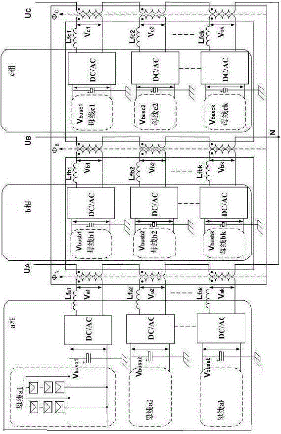
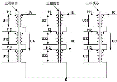
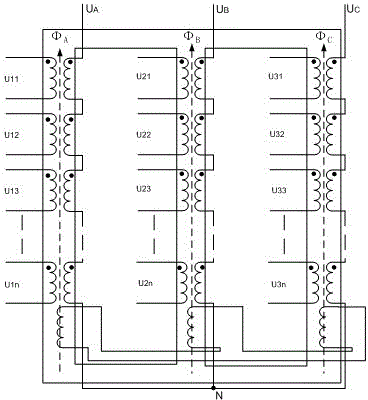
[0018] Such as figure 1 As shown, the specific embodiment of the present invention is to construct a CHB cascaded photovoltaic inverter circuit based on a three-phase multi-split transformer, including a three-phase multi-split transformer and a plurality of CHB cascaded inverter units, the CHB The cascaded inverter unit includes a DC bus, the DC buses of the plurality of CHB cascaded inverter units are multiple independent photovoltaic modules, and the three-phase split transformer is arranged between each inverter unit filter inductor Lf, each of the inverter units is a single-phase full-bridge circuit topology, after converting the current of the independent DC bus into a square wave, the filter inductor Lf filters the square wave into a sine wave containing harmonic components, the sine wave The wave is connected to the three-phase multi-spli...


PUM


Abstract

The invention relates to a CHB cascaded photovoltaic inverter circuit based on a three-phase multi-split transformer. According to the CHB cascaded photovoltaic inverter circuit based on the three-phase multi-split transformer, ground insulation voltage of the current photovoltaic system appliance is not changed, and safe and reliable running of the circuit in a photovoltaic power station can be realized by cascading outputs of a high-power CHB cascaded multi-level photovoltaic inverter through magnetic coupling. A winding on the low-voltage side of the circuit is connected with a plurality of independent inverter outputs with equal power, a split transformer which is used in the circuit is more economic, smaller in occupation area and more convenient in maintenance and management than a plurality of ordinary transformers. The current resistant value of a key device is reduced, and parallel connection of IGBTs (Insulated Gate Bipolar Translators) is avoided.

Description

technical field [0001] The invention relates to a CHB cascaded photovoltaic inverter circuit, in particular to a CHB cascaded photovoltaic inverter circuit based on a three-phase multi-split transformer. Background technique [0002] At present, most inverter devices operating in high-power photovoltaic power plants adopt a two-level three-phase half-bridge inverter topology, and the output is connected to an isolation transformer circuit structure. The two-level three-phase half-bridge inverter topology is simple and easy to control, but it has the following disadvantages: 1. The harmonic content of the two-level output is high, and LC or LCL filters are required, which increases the volume and weight of the inverter device. The efficiency is lower than the multi-level inverter, and the phenomenon of LC resonance will appear. 2. High-power photovoltaic modules occupy a large area and are controlled by one MPPT. The mismatch of power supply of modules has a great impact on ...

Claims


Application Information

Patent Timeline
Patent Type & Authority Patents(China)
IPC IPC(8): H02M7/537
CPCY02E10/56
Inventor 谷宇邢浩江王毅张东来吴斌张华
Owner SHENZHEN ACAD OF AEROSPACE TECH
Why Eureka
Try Eureka