Displacement sensor traveling positioning device

A displacement sensor and positioning device technology, applied in shearing devices, accessories of shearing machines, measuring/indicating equipment, etc., can solve the problem of unstable relative position between the displacement sensor and the induction coil, and improve the width accuracy and position information. precise effect

Active Publication Date: 2015-03-11
LAIWU IRON & STEEL GRP
View PDF6 Cites 0 Cited by
  • Summary
  • Abstract
  • Description
  • Claims
  • Application Information

AI Technical Summary

Problems solved by technology

[0007] In order to solve the above technical problems, the present invention provides a displacement sensor walking positioning device to solve the problem that the relative position between the displacement sensor and the induction coil is extremely unstable in the prior art, and to improve the accuracy and stability of the shear width of the steel plate

Method used


Image

  • Displacement sensor traveling positioning device
  • Displacement sensor traveling positioning device
  • Displacement sensor traveling positioning device

Examples


Embodiment 1

[0034] The embodiment of the invention discloses a displacement sensor walking positioning device, so as to keep the relative position of the strip displacement sensor and the induction coil unchanged.

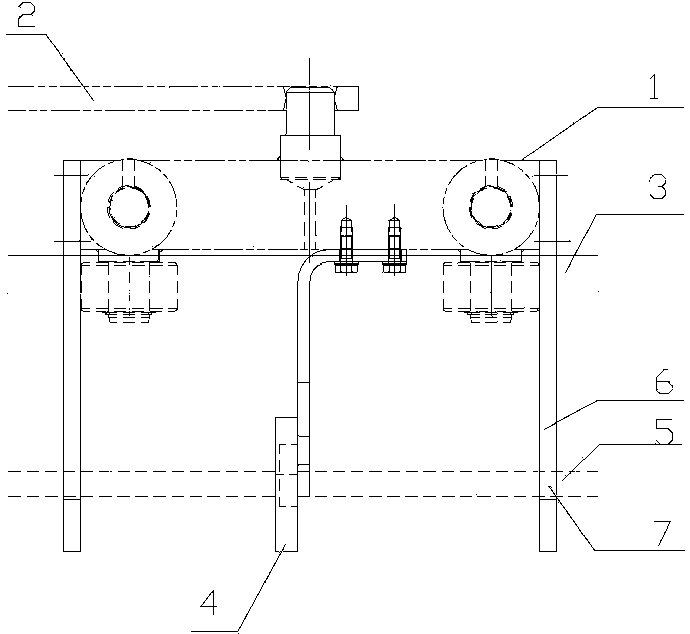
[0035] figure 2 Embodiment 1 of the present invention discloses a displacement sensor walking positioning device.

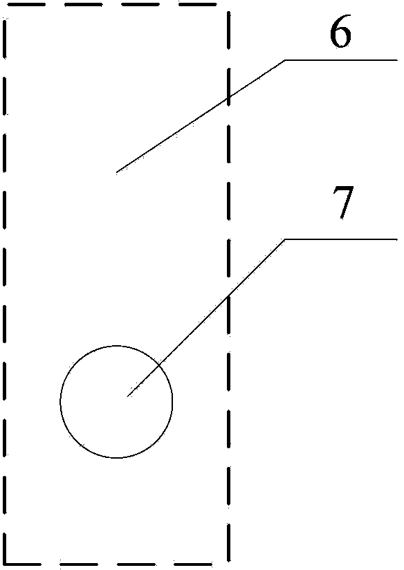
[0036] image 3 It is the position diagram of the through hole on the fixed plate.

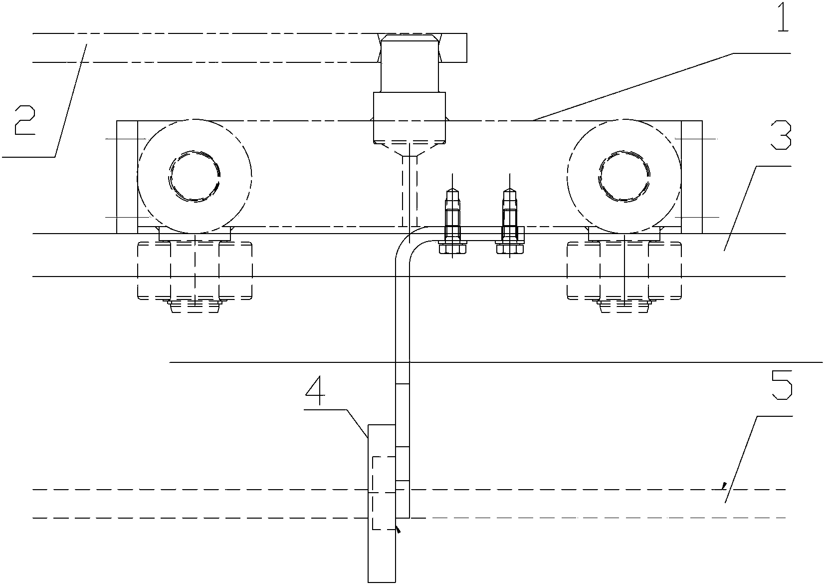
[0037] see figure 2 with image 3 , the displacement sensor walking positioning device may include: a walking trolley 1, a walking trolley fixing device 2, a slide rail 3, an induction coil 4, and may also include: a strip displacement sensor 5 and a fixing plate 6;

[0038] The walking trolley fixing device 2 is connected with the walking trolley 1, so that the walking trolley 1 remains stable during walking;

[0039] The slide rail is located below the walking trolley, and is used for the walking trolley 1 to walk;

[0040] The induction coil 4 is fixed on the bottom of...


PUM


Abstract

The invention discloses a displacement sensor traveling positioning device comprising a traveling cart, a traveling cart fixing device, a slide rail and induction rings. The displacement sensor traveling positioning device further comprises strip-shaped displacement sensors and fixed plates. The fixed plates are respectively vertically fixed at the front end and the rear end of the traveling cart and provided with through holes at the lower ends. The strip-shaped displacement sensors penetrate through the through holes and the induction rings and are supported by the through holes. During steel rolling, the strip-shaped displacement sensors vibrate along with the induction rings, relative positions of the strip-shaped displacement sensors and the induction rings are kept fixed, and accordingly, position information of plates detected by the strip-shaped sensors is more accurate, and width accuracy of the plates is improved.

Description

technical field [0001] The invention relates to a walking positioning device, in particular to a displacement sensor walking positioning device. Background technique [0002] In the production process of the steel plate, it is necessary to cut and trim the steel plate, and cut different positions of the plate into different widths according to the design requirements. When cutting the board for cutting, the walking positioning device detects the position information of the board in real time, and sends the position information to the cutting body control device, and then the cutting body control device controls the cutting width of the cutting body, so that the board Cut to a predetermined shape. [0003] figure 1 It is a structural diagram of a walking positioning device in the prior art. [0004] see figure 1 , in the prior art, the trolley positioning device includes a trolley 1, a trolley fixing device 2 for fixing the trolley, a slide rail 3 positioned below the tro...

Claims


Application Information

Patent Timeline
Patent Type & Authority Patents(China)
IPC IPC(8): B23Q17/22B23D33/00
Inventor 徐强孟祥瑞宋程文刘宝生田遵建阴法亮朱向青孟兆成
Owner LAIWU IRON & STEEL GRP
Why Eureka
Try Eureka