System for dynamically tracking the location of network devices to enable emergency services

a network device and dynamic tracking technology, applied in the field of computer networks, can solve the problems of inability to accurately identify the inability to dynamically discover and report the location of the network entity or the device, and the inability to perform the creation of such manual inventories

Inactive Publication Date: 2007-03-08
CISCO TECH INC
View PDF24 Cites 29 Cited by
  • Summary
  • Abstract
  • Description
  • Claims
  • Application Information

AI Technical Summary

Benefits of technology

[0017] If an emergency call, such as a 911 call, is made from the network entity, the entity's location information is retrieved from the central repository and appended to the call. As a result, emergency personnel are provided with accurate location information of the specific network entity from which the emergency call was placed. The location information can be retrieved by the network entity itself as part of the emergency call procedure or by one or more intermediate network device's used to route the call to the emergency personnel.

Problems solved by technology

Because the creations of such manual inventories are so time consuming, they are rarely performed.
They are also error-prone, resulting in the data base having incorrect information.
For organizations using a private branch exchange (PBX) telephone switch, however, subscriber information is often limited to the organization's name and its main address.

Method used


Image

  • System for dynamically tracking the location of network devices to enable emergency services
  • System for dynamically tracking the location of network devices to enable emergency services
  • System for dynamically tracking the location of network devices to enable emergency services

Examples


Embodiment Construction

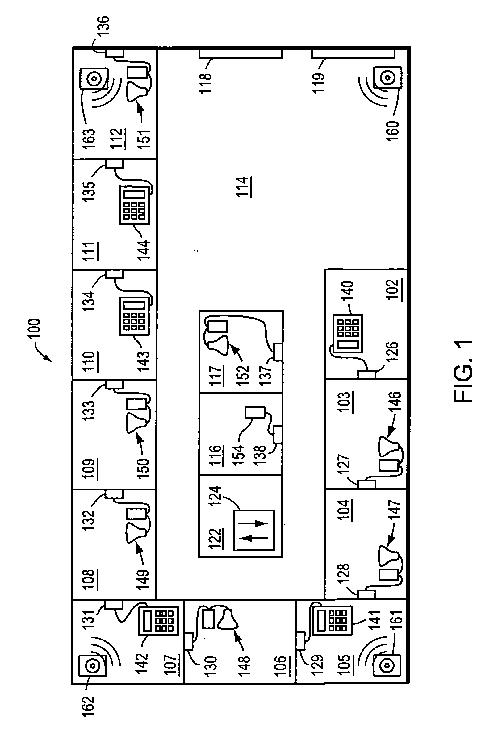
[0025]FIG. 1 is a plan view of an exemplary office layout 100. The office layout 100 includes a plurality of offices 102-112, a lobby 114 and two cubicles 116-117. Disposed along an exterior wall of the lobby 114 are two windows 118-119. The office layout 100 further includes a wiring closet 122. Located within the wiring closet 122 are one or more intermediate network devices, such as a network switch 124. Disposed within each office 102-112 and within each cubicle 116-117 is a network connector or outlet 126-138. The network outlets 126-138 are all radially wired to the wiring closet 122 in a conventional manner. In particular, each outlet 126-138 is preferably coupled to a respective port of the network switch 124.

[0026] Also disposed within each office 102-112 and within each cubicle 116-117 is one or more network entities that are connected to the respective outlet 126-138. For example, disposed within offices 102, 105, 107, 110 and 111, is a Voice over Internet Protocol (VoIP...


PUM


Abstract

A system and / or method to determine the location within a building of an apparatus, such as a personal computer, coupled to a computer network. A communication facility of the apparatus is configured to source and sink messages in the computer network via at least one network port coupled to the computer network. A radio frequency (RF) receiver of the apparatus is configured to receive beacon signals transmitted by a plurality of base stations, the base stations located in the building, each beacon signal encoded with location information descriptive of the location of one of the base stations. Also, a location determination engine of the apparatus is configured to compute a location of the apparatus based on the location information encoded in the beacon signals, the computed location being a point within the building.

Description

CROSS-REFERENCE TO RELATED APPLICATION [0001] The present application is a continuation of U.S. patent application Ser. No. 09 / 908,341, which was filed on Jul. 18, 2001, by David Oran and Silvano Gai, for a SYSTEM FOR DYNAMICALLY TRACKING THE LOCATION OF NETWORK DEVICES TO ENABLE EMERGENCY SERVICES. [0002] The present application is also related to U.S. patent application Ser. No. 09 / 884,239, now issued as U.S. Pat. No. 6,665,611, which was filed on Jun. 19, 2001, by David Oran and Silvano Gai for a SYSTEM FOR DISCOVERING AND MAINTAINING GEOGRAPHIC LOCATION INFORMATION IN A COMPUTER NETWORK TO ENABLE EMERGENCY SERVICES, which is hereby incorporated by reference in its entirety.BACKGROUND OF THE INVENTION [0003] 1. Field of the Invention [0004] This invention relates to computer networks, and more specifically, to a system for dynamically discovering and reporting the location of network entities or devices. [0005] 2. Background Information [0006] Computer networks typically comprise...

Claims


Application Information

Patent Timeline
Patent Type & Authority Applications(United States)
IPC IPC(8): G06F15/16
CPCH04M11/04H04M2242/04H04W76/007H04W4/22H04W64/00H04W4/04H04W4/90H04W76/50
Inventor ORAN, DAVIDGAI, SILVANO
Owner CISCO TECH INC
Why Eureka
Try Eureka