
A chain-belt drive system

A chain belt drive and chain belt technology, applied in the field of chain belt drive system, can solve the problems affecting the normal operation and use of roller moving slat conveyor equipment, and achieve the effect of avoiding tooth loss and ensuring synchronization.

Active Publication Date: 2015-09-30
SHILIN LUOHE METALLURGY EQUIP
View PDF8 Cites 0 Cited by
  • Summary
  • Abstract
  • Description
  • Claims
  • Application Information

AI Technical Summary

Problems solved by technology

These defects have affected the normal operation and use of roller mobile apron conveyor equipment

Method used


Image

  • A chain-belt drive system
  • A chain-belt drive system
  • A chain-belt drive system

Examples


Embodiment Construction

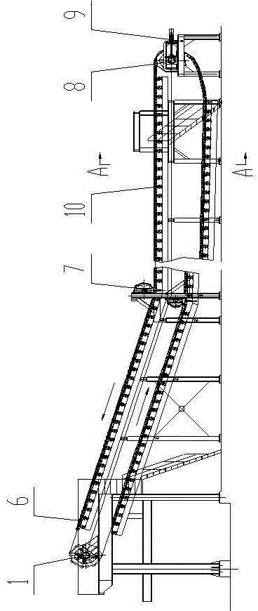
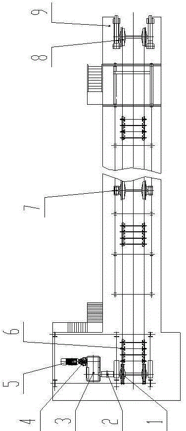
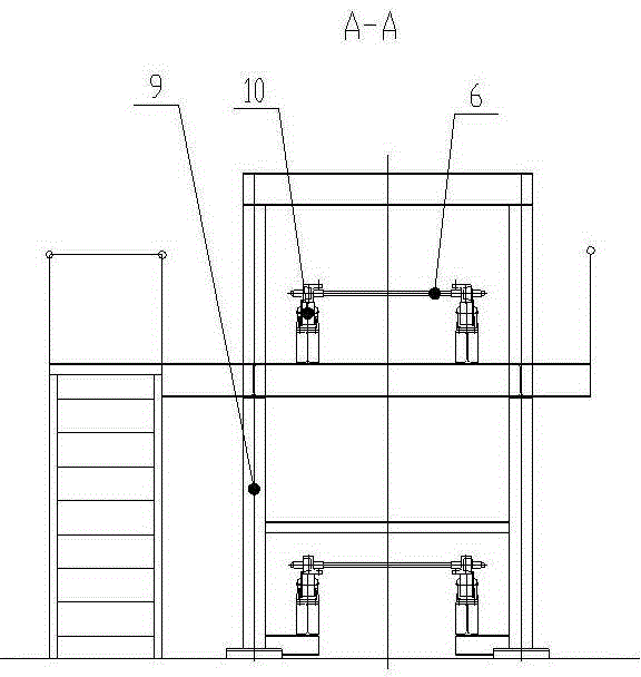
[0041] Such as figure 1 , figure 2 , image 3 As shown, the chain-belt transmission system of the chain-belt tray conveyor is shown. The chain-belt transmission system includes: a driving device, a driving sprocket 1, a chain belt 6, a guide wheel 7, and a driven wheel 8.

[0042] The driving device includes a motor 5, a hydraulic coupling 4, and a reducer 3. The motor 5 and the reducer 3 are connected through the hydraulic coupling 4. The hydraulic coupling 4 can prevent equipment from being damaged due to overloading. The motor 5 drives the reducer 3 through the hydraulic coupling, and connects the driving sprocket 1 through the coupling 2. The driving sprocket 1 drives the driven wheel 8 to run through the chain belt 6. At the turning position of the chain belt 6, in order to prevent the running chain Belt 6 jumps and guide wheel 7 is set. The chain belt 6 is supported by rollers 10 mounted on the equipment stand 9 .

[0043] Such as Figure 4 , Figure 5 As shown, ...


PUM


Abstract

The invention discloses a chain belt driving system installed on a chain belt tray-type conveyor. The chain belt driving system comprises a driving device, left and right drive sprockets, left and right driven wheels, left and right parallel chains and left and right guide wheels, wherein the left and right drive sprockets are connected with and drive the left and right driven wheels, a left guide wheel and a right guide wheel are arranged at junctions of the horizontal sections and inclining sections of the go path and the return path of the chain belt respectively, and the drive sprocket is driven by the drive device. The chain belt driving system is characterized in that the drive sprockets and the parallel chains form an integral structure to ensure the synchronization of the chain belt in running, and the driven wheels and the guide wheels are of toothless unilateral high-shrouded structure to prevent the deviation and off-road of the chain belt. The integrated structure of the chain belt has the upper plane and the lower plane which are integrated, so that spreading iron blocks or iron slag cannot jam into the chain plate, and the chain belt cannot be broken due to jamming of the chain plate when the chain plate runs towards the drive sprockets. The chain belt driving system has the advantages of high efficiency, safe and reliable operation, and can also be applied on a wheel fixed pig-casting machine to significantly improve effect of the pig-casting machine.

Description

technical field [0001] The invention relates to a chain-belt drive system used on a chain-belt pallet conveyor. Background technique [0002] In the iron production process of the iron and steel industry, cast iron equipment continuously pours the smelted high-temperature molten iron into iron nuggets, and the fallen iron nuggets are transported to the iron nugget stacking yard for storage through the iron nugget conveying system, which is convenient for the production and later application of iron nuggets. [0003] The current iron nugget conveying system includes car direct transport, locomotive direct transport and roller moving rotary slat conveyor. [0004] When the cast iron production area is small, the iron blocks produced need to be transported out. At present, the roller moving rotary apron conveyor is mainly used. The working process of the roller moving rotating apron conveyor is: the iron blocks falling from the cast iron machine fall through the fixed iron chu...

Claims


Application Information

Patent Timeline
Patent Type & Authority Patents(China)
IPC IPC(8): B65G17/12B65G23/06B65G23/24B65G17/42
Inventor 冯力滕伟强刘永桀刘升强李凤
Owner SHILIN LUOHE METALLURGY EQUIP
Learn More