
A chain belt tray device

A pallet and chain belt technology is applied in the field of chain belt pallet devices to achieve the effect of large conveying capacity and avoiding safety accidents.

Active Publication Date: 2015-11-18
SHILIN LUOHE METALLURGY EQUIP
View PDF8 Cites 0 Cited by
  • Summary
  • Abstract
  • Description
  • Claims
  • Application Information

AI Technical Summary

Problems solved by technology

[0008] The present invention aims to solve the above-mentioned technical problems existing in the working conditions of the existing roller-moving rotary apron conveyor, and provides a chain-belt tray device for the chain-belt tray conveyor, which can significantly improve the quality of iron blocks, minerals or block materials Improve the efficiency and safety performance of the conveyor, improve production efficiency, and prevent safety accidents caused by broken chain belts

Method used


Image

  • A chain belt tray device
  • A chain belt tray device
  • A chain belt tray device

Examples


Embodiment Construction

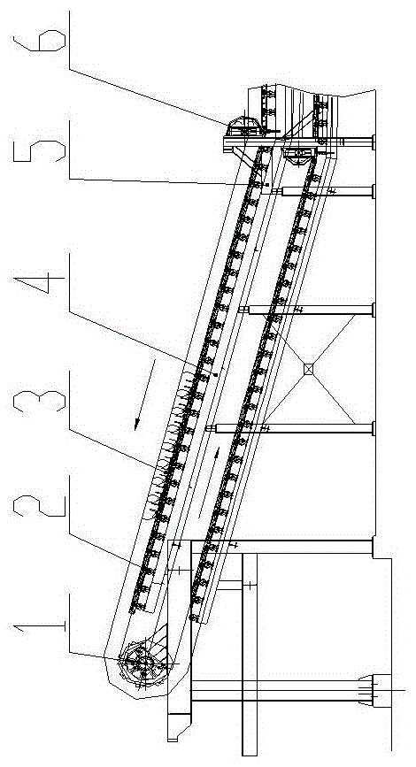
[0033] figure 1 As shown, a chain belt tray device 3 is arranged on the chain belt tray conveyor, supported on the roller 2 of the roller base 4 of the conveyor frame 5, the chain belt tray device 3 is driven by the driving sprocket 1 to run, The corner of the tray device 3 presses the left and right chain plates of the chain belt device through the guide wheel 6 to prevent the chain plate from lifting up with the tray under the action of the driving force when the chain belt tray device 3 moves, causing the chain belt to detach from the rollers The track formed by the device 2 causes the chain belt to deviate, which affects the normal production of the chain belt pallet conveyor.

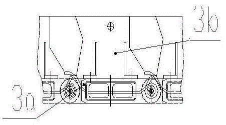
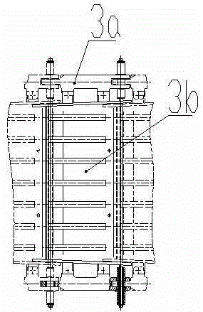
[0034] Such as figure 2 , image 3 and Figure 4 As shown, the chain belt tray device 3 is made up of a chain belt 3a and a duckbill U-shaped tray 3b. The iron block falls on the duckbill U-shaped tray 3b, and the tray 3b is driven to run along with the chain belt 3a. The duckbill U-shaped t...


PUM


Abstract

The invention discloses a chain belt tray device which mainly comprises a chain belt and a duckbill U-shaped tray supported by the chain belt. The duckbill U-shaped tray is provided with a duckbill U-shaped bottom plate, left and right side plates are arranged on the left and right side of the duckbill U-shaped bottom plate, left and right connecting plates and the connecting plate are fixed on the outer side of the left and right side plates, the overall shape of the duckbill U-shaped bottom plate is of ladder structure with small front end and big rear end. The device applied on a chain belt tray-type conveyor adopts the duckbill U-shaped tray, and the duckbill of the rear duckbill U-shaped tray overlaps and covers the tail of the front duckbill U-shaped tray. During running of the chain belt tray type conveyor, small iron blocks and iron slag cannot be jammed into the gap between two trays to cause unpredictable block and deformation of the tray. The chain belt tray device has the advantages of effectively preventing deformation or breakage of the chain belt due to the fact that the splashing small iron blocks and iron slag or other small particulate mineral or the bulk material jam into the chain belt, so that the normal continuous production of the equipment is guaranteed, and safety accidents are avoided.

Description

technical field [0001] The invention relates to a chain-belt pallet device for a chain-belt pallet conveyor. Background technique [0002] In the ironmaking production process of the iron and steel industry, the cast iron machine equipment continuously pours the smelted high-temperature molten iron into iron nuggets, but when the cast iron production area is small, the produced iron nuggets need to be transported out, and the fallen iron nuggets pass through the iron nugget conveying system It is transported to the iron block storage yard for storage, which is convenient for the production and later application of iron blocks. [0003] At present, the iron block conveying system mainly adopts the roller moving rotating apron conveyor. The working process of the roller moving rotating apron conveyor is: the iron blocks falling from the cast iron machine fall through the fixed iron chute and the receiving hopper of the roller moving rotating apron conveyor to the supporting p...

Claims


Application Information

Patent Timeline
Patent Type & Authority Patents(China)
IPC IPC(8): B65G17/12B65G17/36B65G17/42
Inventor 冯力刘升强滕伟强
Owner SHILIN LUOHE METALLURGY EQUIP
Learn More