Hydraulic rotary joint

A rotary joint and hydraulic technology, applied in the direction of flexible/rotatable line connectors, connections, electrical components, etc., can solve the problems of easy oil leakage of rotary joints, influence of rotary body and rotary shaft, short life of pipelines, etc., to ensure high performance, reduced labor intensity, and long pipeline life

Inactive Publication Date: 2013-04-24
JIANGSU CHANGLING HYDRAULIC CO LTD
View PDF0 Cites 5 Cited by
  • Summary
  • Abstract
  • Description
  • Claims
  • Application Information

AI Technical Summary

Problems solved by technology

[0003] However, after the conventional swivel joints connect the hydraulic pipelines and circuits of the fixed part and the rotating part in the hydraulic system and the circuit, the relative rotation angle of the fixed part and the rotating part is generally 50° to 80°, and the rotation angle is small, so the operation and maintenance are not easy. Convenience, and interference between pipelines is easy to occur, resulting in short pipeline life
[0004] Moreover, the sealing performance between the rotary joint and the outside world in the past is poor, and the dust from the outside is easy to drill into the rotary joint, which affects the performance of the rotary joint, and the oil in the rotary joint is also easy to leak out, which is difficult for the rotary body and the rotary shaft in the rotary joint. The rotation also has an impact, requiring frequent oiling, which increases the labor intensity of the workers

Method used


Image

  • Hydraulic rotary joint
  • Hydraulic rotary joint
  • Hydraulic rotary joint

Examples


Embodiment Construction

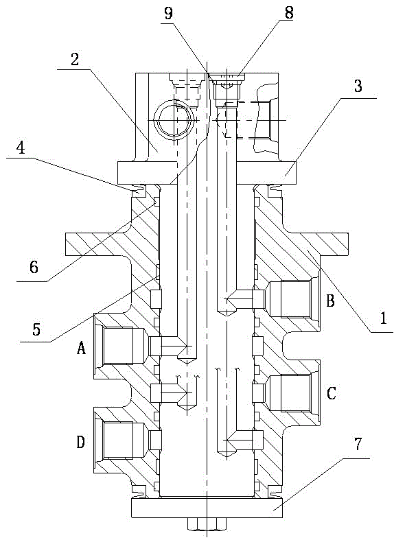
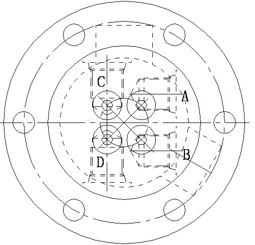
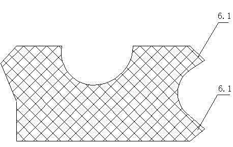
[0015] see Figure 1 to Figure 3 , the present invention relates to a hydraulic rotary joint, comprising a rotary body 1 and a rotary shaft 2, the bottom end of the rotary shaft 2 is axially inserted from the top end of the rotary body 1, and the top end of the rotary shaft 2 is exposed from the rotary body 1, A flange 3 is provided between the top of the rotary body 1 and the rotary shaft 2, a water seal ring 4 is provided between the bottom surface of the flange 3 and the top of the rotary shaft 2, and a water seal ring 4 is provided at the bottom of the rotary shaft 2. There is a bottom plate 7, and the bottom plate 7 is fixed to the bottom end of the rotary shaft 2 through bolts and washers, and a rotary sealing ring 5 and a dustproof sealing ring 6 are installed in the annular groove between the rotary body 1 and the rotary shaft 2. The side of the dust-proof sealing ring 6 in contact with the rotary shaft 2 is provided with two upper and lower lips 6.1 to form a double l...


PUM


Abstract

The invention relates to a hydraulic rotary joint comprising a rotary body (1) and a rotary shaft (2). The hydraulic rotary joint is characterized in that the bottom end of the rotary shaft (2) is axially inserted from the top end of the rotary body (1), the top end of the rotary shaft (2) extends out of the rotary body (1), a flange (3) is arranged between the top end of the rotary body (1) and the rotary shaft (2), a rotary sealing ring (5) and a dustproof sealing ring (6) are arranged in a circular groove between the rotary body (1) and the rotary shaft (2), an upper lip and a lower lip (6.1) are arranged on one side of the dustproof sealing ring (6) contacting with the rotary shaft (2) to form double lips, and the upper lip and the lower lip (6.1) are attached to the outer wall of the rotary shaft (2). According to the hydraulic rotary joint, dust is not prone to entering and oil is not prone to leakage. Besides, a rotary angle is large, interference does not exist among pipelines, and operation and maintenance are very convenient.

Description

technical field [0001] The invention relates to a hydraulic rotary joint, which is mainly used in the hydraulic systems of large-tonnage excavators, cranes, graders, tower cranes and other machinery, and is used to connect the hydraulic pipelines and circuits of the fixed part and the rotating part in the entire hydraulic system and circuit. A connector belongs to the technical field of engineering machinery. Background technique [0002] For hydraulic excavators, cranes, loaders, etc., the upper and lower parts need to be rotated, so there is a problem of connecting the oil circuit and the circuit between the rotating part and the fixed part. The rotary joint is composed of a rotary body, a rotary shaft and a cover. When in use, the revolving body is fixed to the revolving lower platform of hydraulic excavators and cranes, and the mounting plate on the revolving shaft is connected with the slewing support on the revolving upper platform. Hydraulic rubber hoses and wires a...

Claims


Application Information

Patent Timeline
Patent Type & Authority Applications(China)
IPC IPC(8): F16L39/06H01R35/00
Inventor 夏泽民张爱军陈酉冰潘逸明高海波朱江华
Owner JIANGSU CHANGLING HYDRAULIC CO LTD
Why Eureka
Try Eureka