Optical mapping method and mapping system thereof

A drawing method and optical technology, applied in the field of optical drawing method and its drawing system, can solve problems such as difficulties

Active Publication Date: 2013-04-24
吴江科技创业园管理服务有限公司
View PDF8 Cites 2 Cited by
  • Summary
  • Abstract
  • Description
  • Claims
  • Application Information

AI Technical Summary

Problems solved by technology

However, such a complicated way of painting is qui

Method used


Image

  • Optical mapping method and mapping system thereof
  • Optical mapping method and mapping system thereof
  • Optical mapping method and mapping system thereof

Examples


Embodiment Construction

[0046] In order to have a further understanding of the purpose, structure, features, and functions of the present invention, the following detailed descriptions are provided in conjunction with the embodiments.

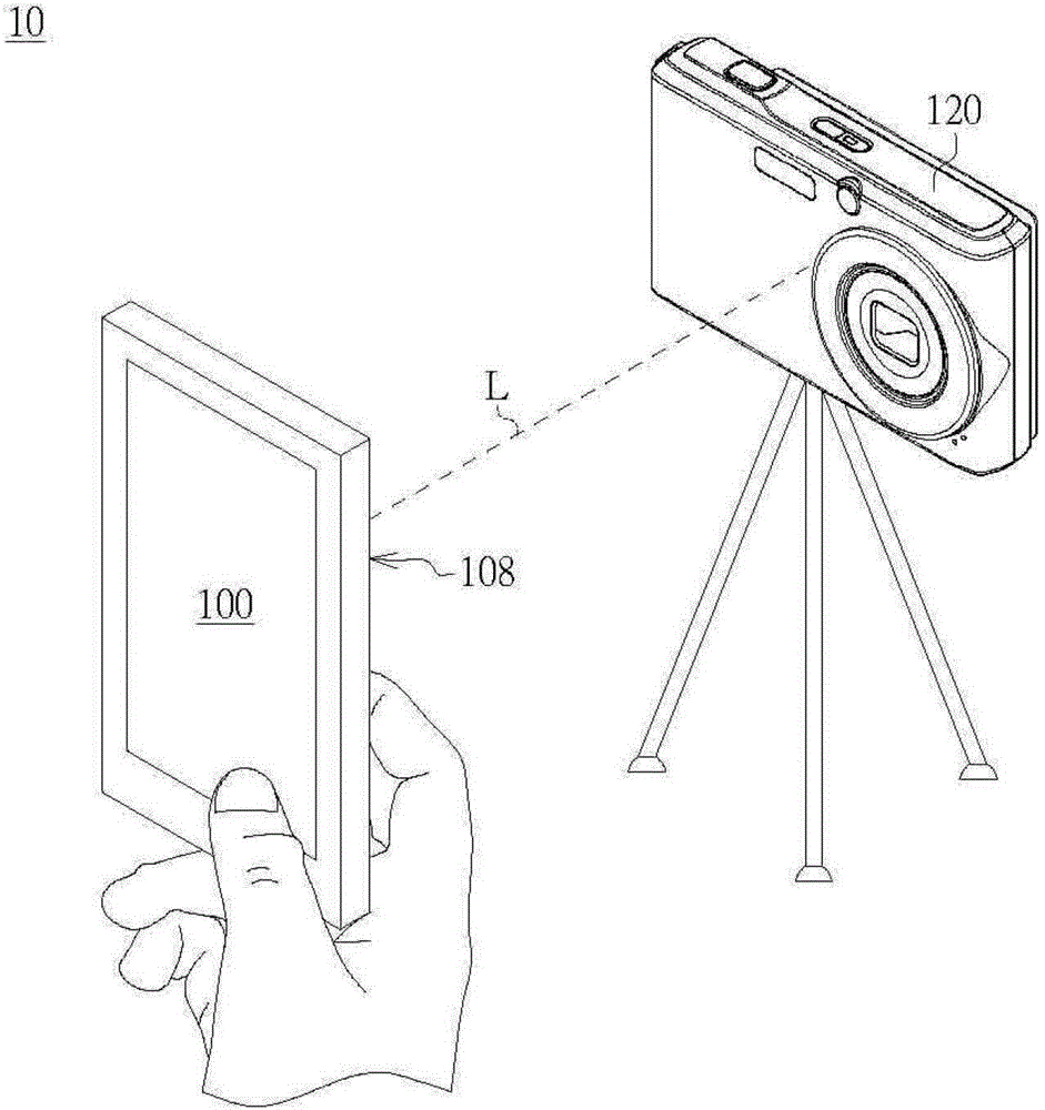
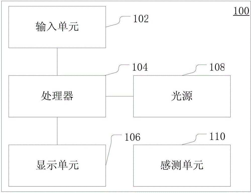
[0047] Such as figure 1 Shown is a schematic diagram of an optical drawing system according to an embodiment of the present invention. The optical drawing system 10 includes a handheld device 100 and a camera device 120 . The handheld device 100 has a light source 108 . For example, the light source 108 is a flash light source or other light emitting units. The light source 108 is used to provide a light beam L. As shown in FIG. The imaging device 120, for example, the imaging device 120 is a camera or a video camera, which has an exposure function, especially a long exposure photography function (Long exposure photography), which can take pictures of the light beam L of the light source 108 at a time interval by opening the shutter for a long time. .

[0048] Such...


PUM


Abstract

The invention provides an optical mapping method. The method includes the following steps: providing a handheld device which comprises an input unit, a processor and a light source, receiving input information by the input unit, conducting image inversion on the input information through the algorithm to obtain an image inversion pattern, outputting promoting message through a processor to prompt a user to move the handheld device according to the image inversion pattern to enable light beams of a light source to form an optical track in a time interval.

Description

technical field [0001] The invention relates to an optical drawing method and a drawing system thereof, in particular to an optical drawing method and a drawing system of a handheld device. Background technique [0002] In recent years, two Japanese designers, Nageta Takeshi and Monno Kazue, have used the exposure function of the camera in a dark environment to capture the light and shadow of a flashlight, presenting a light and shadow trajectory pattern. This method of presenting light and shadow trails is currently called light and shadow graffiti (PiKAPiKA). [0003] To carry out light and shadow graffiti (PiKAPiKA), you need to prepare a camera and a flashlight. One person acts as a photographer, and the other uses a flashlight as a brush as a painter. When the photographer starts the camera for a long exposure, the painter faces the camera and begins to draw, the camera will record the trajectory of the light and shadow of the flashlight, and the exposure will be ended...

Claims


Application Information

Patent Timeline
IPC IPC(8): G06F3/0487G06T11/80
Inventor 周家庆
Owner 吴江科技创业园管理服务有限公司
Why Eureka
Try Eureka