Supercharge Your Innovation With Domain-Expert AI Agents!

Vehicle door latch device

一种车门锁、锁扣的技术,应用在车辆锁、电动车锁、建筑锁等方向,能够解决连接检测开关效率低等问题

Active Publication Date: 2013-05-01
MITSUI KINZOKU ACT
View PDF6 Cites 19 Cited by
  • Summary
  • Abstract
  • Description
  • Claims
  • Application Information

AI Technical Summary

Problems solved by technology

It is also necessary to provide a wire harness for supplying a detection signal from the detection switch to the outside, and the efficiency of connecting the detection switch is low.

Method used


Image

  • Vehicle door latch device
  • Vehicle door latch device
  • Vehicle door latch device

Examples


Embodiment Construction

[0018] An embodiment of the present invention will be described as follows.

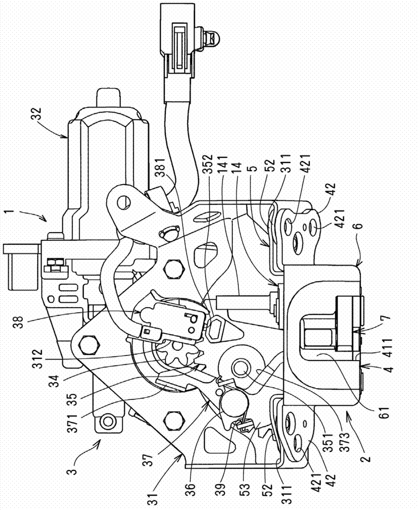
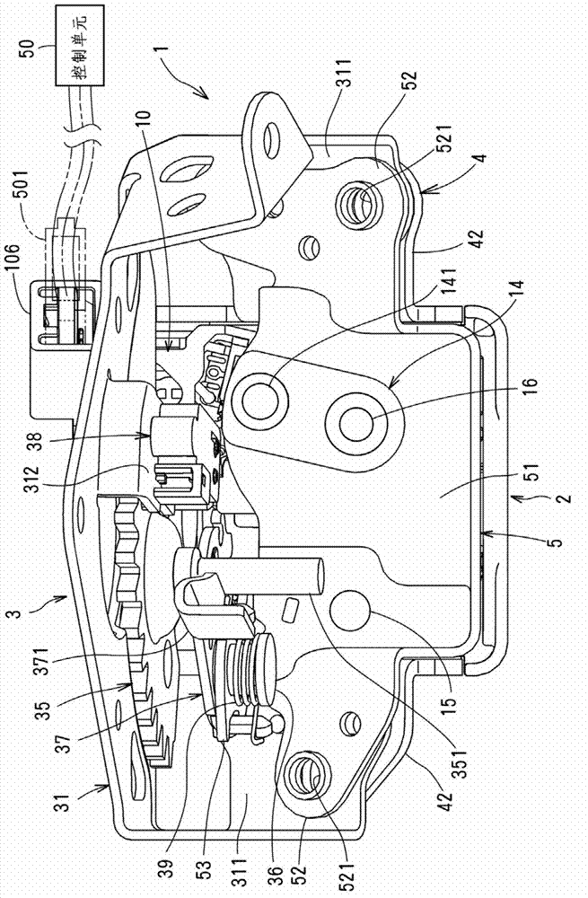
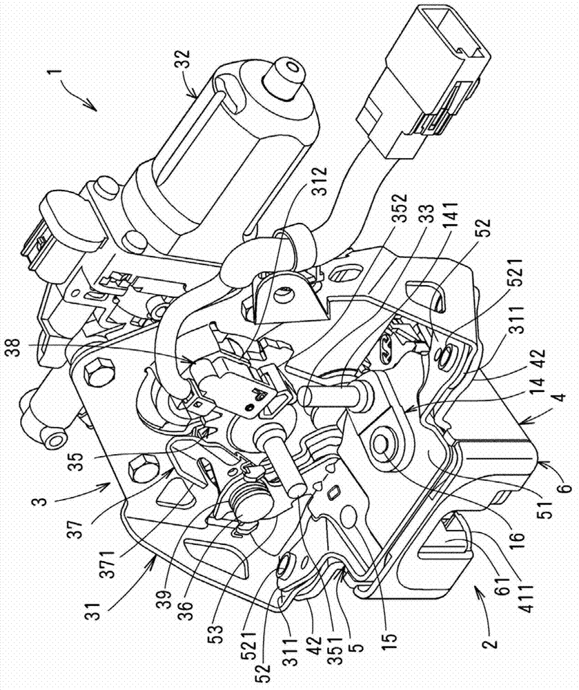
[0019] The door lock device 1 is arranged at the lower end of a liftgate (not shown), which is pivotally connected to the rear of the vehicle body at the upper end through a hinge shaft (not shown), so that it can be vertically On or off. The door lock device 1 includes: an engaging unit 2, Image 6 and Figure 7 Among them, the engaging unit 2 is engaged with the lock catch S installed to the vehicle body, so that the liftgate is kept in the closed state; and the operating unit 3 provides: the closing function, wherein the operating unit 3 makes the engaging unit 2 Electrically switch from a semi-locked state where the liftgate is not fully closed to a fully locked state where the liftgate is completely closed; a release function, which is used to release the engagement of the engaging unit 2, so that the liftgate can be opened.

[0020] The engagement unit 2 includes: a metal cover plate 4 mount...


PUM


Abstract

A vehicle door latch device comprises a base member having a striker-engagement groove which a striker of a vehicle body enters; a latch pivotally mounted to the base member and engagable with the striker; a ratchet pivotally mounted to the base member to engage with the latch to prevent the latch from turning; a latch-detecting switch detecting a turning position of the latch; and a terminal block in which a latch conductive plate is formed by insert molding. The terminal block has a holding portion for the latch-detecting switch without coupling means. The latch conductive plate has a connecting terminal exposed in the holding portion and electrically connected to the latch detecting switch.

Description

technical field [0001] The invention relates to a vehicle door lock device, which includes a detection switch for detecting a locking position. Background technique [0002] The vehicle door lock device includes: a base member fixed to a door; a lock engaged with a striker (striker) of a vehicle body when the door is closed; a lock detection switch for detecting a rotational position of the lock; and a ratchet. The claw (ratchet) detection switch is used to detect the rotational position of the ratchet. As described in JP2004-116042A, the lock detection switch detects the half-locked position of the lock to drive a motor, thereby turning the lock from the half-locked position to the fully locked position, and forcing the door to turn from the slightly open state to the fully closed state. [0003] However, in the above-mentioned door lock device, it is necessary to fix the detection switch to a predetermined position by a connection means such as a bolt. It is also necessa...

Claims


Application Information

Patent Timeline
Patent Type & Authority Applications(China)
IPC IPC(8): E05B65/12E05B85/24E05B79/08E05B81/66E05B81/68
CPCE05B81/36E05B81/20E05B81/66E05B81/68E05C19/12E05B77/40E05B81/54E05B85/02Y10T292/0936
Inventor 横田佳明片川峰孝
Owner MITSUI KINZOKU ACT
Features
  • R&D
  • Intellectual Property
  • Life Sciences
  • Materials
  • Tech Scout
  • Unparalleled Data Quality
  • Higher Quality Content
  • 60% Fewer Hallucinations
Learn More