Drainage stop valve

A technology of stop valve and valve cavity, which is applied in the direction of valve lift, valve detail, valve device, etc., can solve the problem that the control valve cannot realize fast sewage discharge, and achieve the effects of high utilization rate, rapid sewage discharge and high work efficiency

Active Publication Date: 2013-05-01
新乡平原航空液压设备有限公司
View PDF9 Cites 7 Cited by
  • Summary
  • Abstract
  • Description
  • Claims
  • Application Information

AI Technical Summary

Problems solved by technology

[0005] The purpose of the present invention is to provide a sewage cut-off valve to solve the technical problem that the control valve in the prior art cannot realize fast sewage discharge

Method used


Image

  • Drainage stop valve
  • Drainage stop valve

Examples


Embodiment Construction

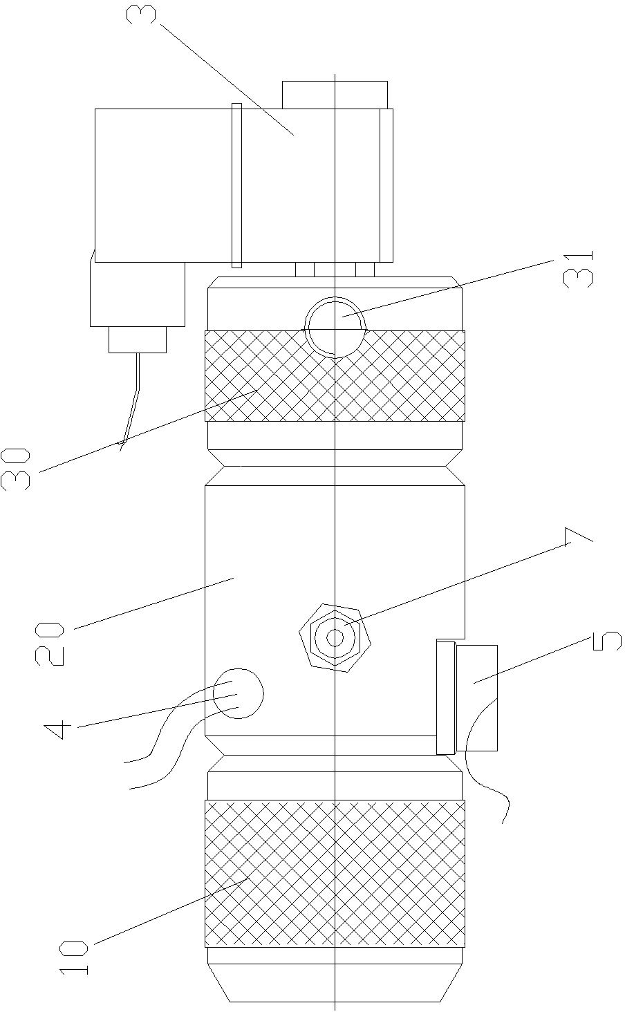
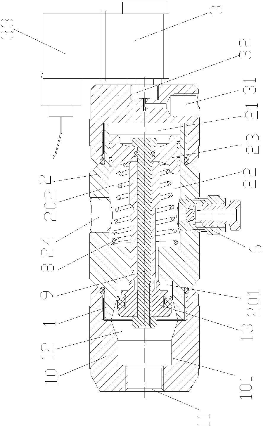
[0017] Such as figure 1 , figure 2 As shown, an embodiment of a sewage shut-off valve, the sewage shut-off valve in this embodiment includes a pilot valve, a piston device 2 and a main valve 1 arranged in sequence from front to back along the front-to-back direction, and the main valve 1 is provided with a valve cavity 12. The valve chamber 12 has an inlet and an outlet, and a spool 13 for controlling the on-off of the inlet and outlet of the valve chamber is installed in the valve chamber 12 to control the opening or closing of the main valve. The sewage cut-off valve has a liquid inlet 24 communicated with the inlet of the valve chamber 12 and a liquid outlet 11 communicated with the outlet of the valve chamber. There is a piston cavity in the piston device 2 here, and a piston 23 is installed to reciprocate along a linear direction in the piston cavity. The piston 23 separates the piston cavity into a first cavity 21 and a second cavity 22. In the front, the second chamb...


PUM


Abstract

The invention discloses a drainage stop valve which comprises a main valve, a piston device and a pilot valve. The main valve is internally provided with a valve cavity which is provided with an inlet, an outlet and a valve core for controlling the inlet and the outlet of the valve cavity to open and close. The drainage stop valve is provided with a liquid inlet communicated with the inlet of the valve cavity and a liquid outlet communicated with the outlet of the valve cavity. The piston device is provided with a piston in synchronous transmission connection with the valve core. The piston divides a piston cavity of the piston device into a first cavity and a second cavity. The pilot valve is provided with a work port communicated with the first cavity. The second cavity of the piston device is communicated with the inlet of the valve cavity through a channel. The liquid inlet of the drainage stop valve is communicated with the second cavity of the piston device through the channel to realize communication with the inlet of the valve cavity. In the moving process of the piston, liquid impurities in the second cavity communicated with the liquid inlet are pushed, so that the liquid impurities flow to the valve cavity quickly and flow out from the liquid outlet through valve cavity so as to drain quickly.

Description

technical field [0001] The invention specifically relates to a blowdown stop valve. Background technique [0002] The liquid impurities filtered out by the filter during the working process accumulate at the bottom of the filter housing, and the accumulation of liquid impurities will cause the filter to block and affect the normal operation of the filter. The traditional method is to set up a drain hole at the bottom of the filter, and the drain hole is detachably equipped with a plug. During sewage discharge, the plug is manually removed to realize sewage discharge. However, this traditional method has low sewage discharge efficiency and is not suitable for applications in places with harsh working conditions because manual operations are required. [0003] Usually, a sewage channel is connected to the sewage hole of the filter, and a control valve for controlling the on-off of the sewage channel is arranged on the sewage channel. An electro-hydraulic control valve, the e...

Claims


Application Information

Patent Timeline
Patent Type & Authority Applications(China)
IPC IPC(8): F16K1/00F16K31/122F16K49/00
Inventor 胡振磊张中明谢宪旺
Owner 新乡平原航空液压设备有限公司
Why Eureka
Try Eureka