
Roll-paper use-up detection device and printing device and roll-paper use-up detection method

A detection device, printing equipment technology, applied in the direction of printing device, printing, etc., can solve the problem of incomplete printing content of ticket paper, trouble, increase of users, etc.

Active Publication Date: 2013-05-08
SHENZHEN JOYSCAN TECH
View PDF7 Cites 2 Cited by
  • Summary
  • Abstract
  • Description
  • Claims
  • Application Information

AI Technical Summary

Problems solved by technology

[0003] This roll paper exhaustion detection device is usually only able to detect a certain amount of remaining roll paper. When the user receives the message that the paper is almost exhausted, he needs to pay attention to whether the roll paper is used up at any time, so as to avoid the printing content of the ticket paper being insufficient. The complete situation has increased unnecessary troubles for users
Or the alarm signal can only be issued when the roll paper has been used up, resulting in incomplete printing.
Therefore, the detection result of the above-mentioned roll end detection device is not accurate

Method used


Image

  • Roll-paper use-up detection device and printing device and roll-paper use-up detection method
  • Roll-paper use-up detection device and printing device and roll-paper use-up detection method
  • Roll-paper use-up detection device and printing device and roll-paper use-up detection method

Examples


Embodiment Construction

[0039] The roll paper end detection device, the printing equipment and the roll paper end detection method will be further described in detail below with reference to the embodiments and the accompanying drawings.

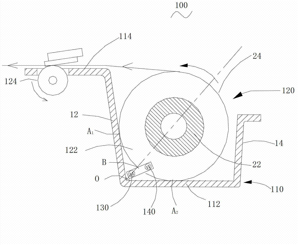
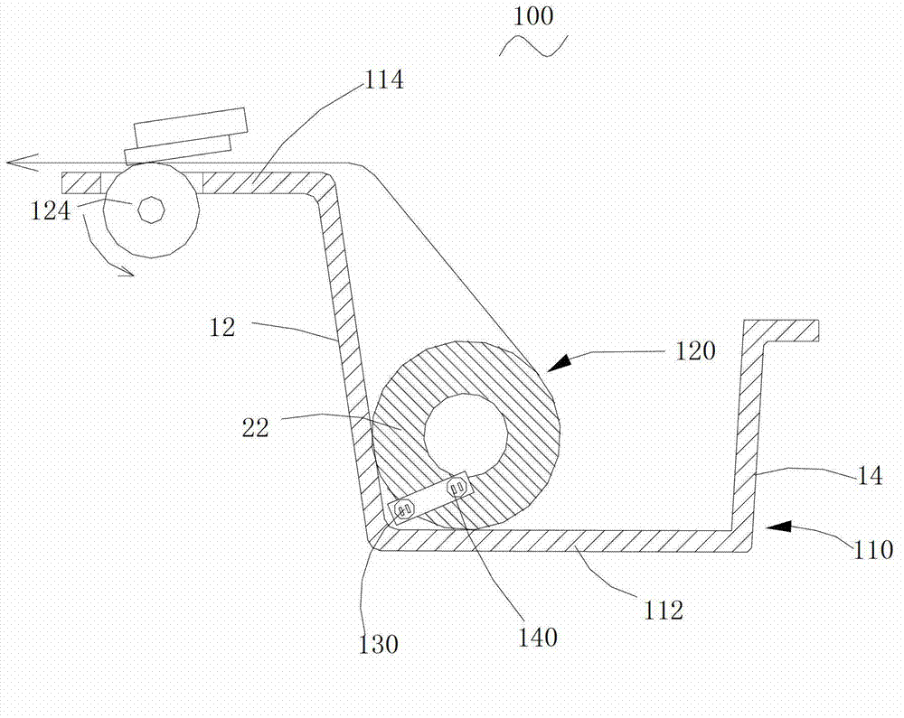
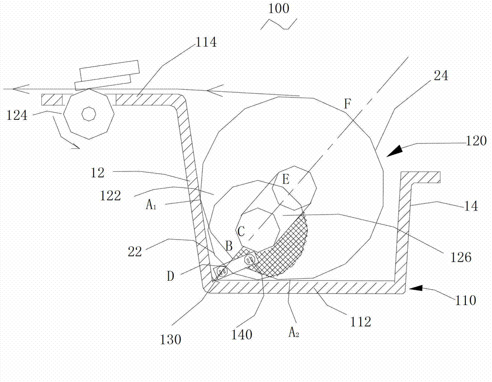
[0040] see figure 1 , the roll paper end detection device 100 of an embodiment includes a paper bin 110 , a roll paper assembly 120 , a first photoelectric sensor 130 and a second photoelectric sensor 140 .

[0041] The shape of the paper bin 110 is a square box, which includes a substantially square bottom wall 112 and four side walls connected to the four edges of the bottom wall 112, which are respectively a left side wall 12, a right side wall 14, and a front side wall. (not shown) and rear side wall (not shown). The bottom wall 112 and the four side walls form an open warehouse for storing roll paper. The bottom wall 112 and the four side walls can be integrally formed to simplify the assembly process. In other embodiments, the right side wall, front side w...


PUM


Abstract

A roll-paper use-up detection device comprises a paper bin, a roll-paper component, a first photoelectric sensor and a second photoelectric sensor, wherein the paper bin is used for containing roll paper and comprises a bottom wall and a side wall connected with the edge of the bottom wall; the roll-paper component comprises the roll paper and a printing roller, the roll paper is installed inside the paper bin, the printing roller is installed on the side wall, the printing roller drives the roll paper to move and rotate towards the direction of the side wall close to the paper-outlet side, and paper sheets of the roll paper are enabled to move out of the paper bin; the first photoelectric sensor is installed inside the paper bin and close to a connection position of the bottom wall and the side wall on the paper outlet side; the detection area of the first photoelectric sensor is located outside the maximum cross section of the roll paper and is overlapped with the minimum cross section of the roll paper; and the second photoelectric sensor is installed inside the paper bin and adjacent to the first photoelectric sensor, and the detection area of the second photoelectric sensor is overlapped with the maximum cross section and the minimum cross section of the roll paper. Detection results of the roll-paper use-up detection device are accurate, no complex structures are added, and inconvenience caused by the fact that roll paper cannot be replaced in time when used up is avoided. The invention further provides a printing device and a roll-paper use-up detection method.

Description

technical field [0001] The invention relates to the field of printing equipment, in particular to a roll paper exhaustion detection device, a printing equipment and a roll paper exhaustion detection method. Background technique [0002] Roll paper is widely used in printing equipment such as supermarkets, shopping malls, and hospitals. When using this kind of printing equipment, the general working time is longer, the workload is larger, and the roll paper needs to be replaced frequently. In order to prevent printing out of paper, it will cause adverse effects on work and printing equipment. Generally, it is necessary to prompt to replace the roll paper when the roll paper is about to run out. Usually, a roll paper end detection device is installed on the side wall of the paper compartment of the printing device, and when the remaining volume of the roll paper reaches a preset value, an alarm signal is sent to prompt the user to replace the roll paper. [0003] This roll ...

Claims


Application Information

Patent Timeline
Patent Type & Authority Applications(China)
IPC IPC(8): B41J29/48
CPCB41J29/48B41J11/0075B41J15/042
Inventor 樊小明孙运金
Owner SHENZHEN JOYSCAN TECH
Learn More