See-through display brightness control

A see-through display and see-through display technology, applied to static indicators, cathode ray tube indicators, instruments, etc., can solve problems such as discomfort or damage to the user's eyes

Active Publication Date: 2013-05-08
MICROSOFT TECH LICENSING LLC
View PDF4 Cites 73 Cited by
  • Summary
  • Abstract
  • Description
  • Claims
  • Application Information

AI Technical Summary

Problems solved by technology

Also, if too much light is used to display the imag

Method used


Image

  • See-through display brightness control
  • See-through display brightness control
  • See-through display brightness control

Examples


Embodiment Construction

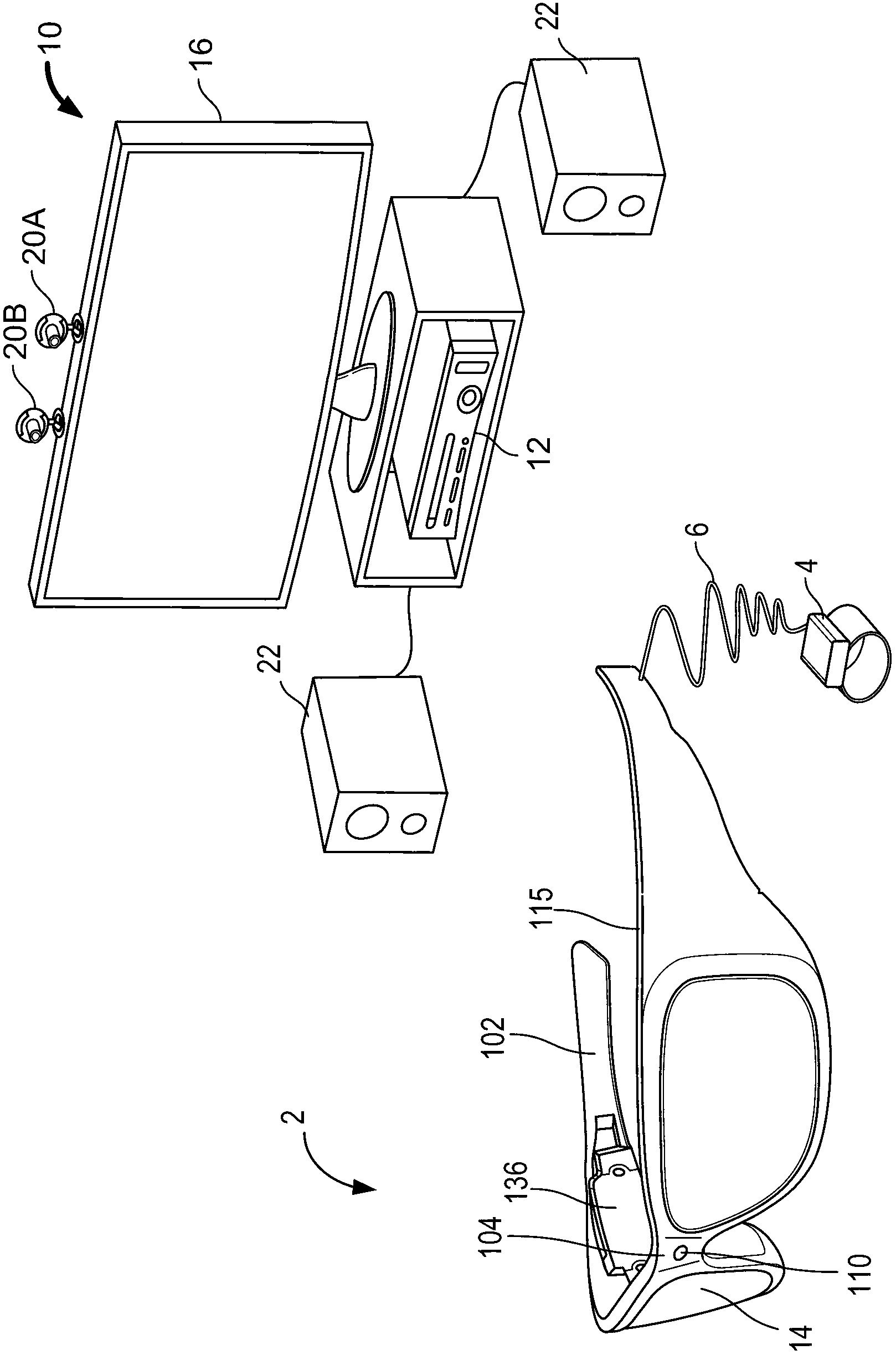
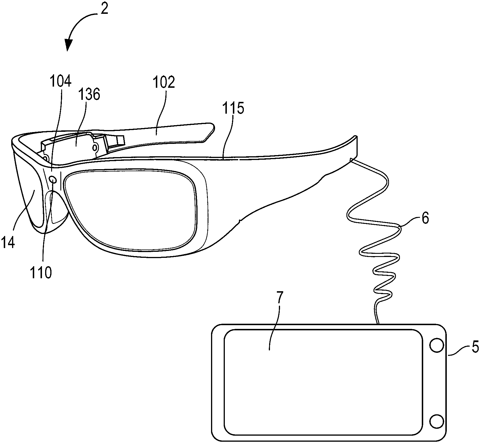
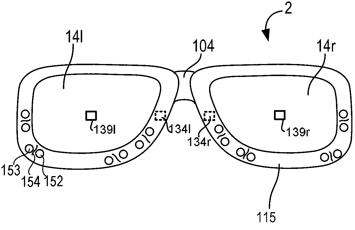
[0053] The techniques described herein provide various embodiments for adjusting the brightness of see-through, near-eye displays. One possible adjustment is to change the brightness used to display the image ("image brightness"). Another possible adjustment is to change the opacity of the display so that more or less external light will pass through into the wearer's eyes. These adjustments can be balanced against each other so that real and virtual objects are properly viewed.

[0054] In one embodiment, the wearer's eyes are tracked to determine where the user is looking. The light intensity of the real world object the user is looking at is then determined. Light intensity can be used to adjust opacity and / or image brightness. In one embodiment, the wearer's pupil size is tracked. Pupil size can be used to determine how to adjust opacity and / or image brightness. Note that both light intensity from the object and pupil size can be taken into account in the determinatio...


PUM


Abstract

The technology provides various embodiments for controlling brightness of a see-through, near-eye mixed display device based on light intensity of what the user is gazing at. The opacity of the display can be altered, such that external light is reduced if the wearer is looking at a bright object. The wearer's pupil size may be determined and used to adjust the brightness used to display images, as well as the opacity of the display. A suitable balance between opacity and brightness used to display images may be determined that allows real and virtual objects to be seen clearly, while not causing damage or discomfort to the wearer's eyes.

Description

technical field [0001] The invention relates to a see-through display, in particular to brightness control of the see-through display. Background technique [0002] Augmented or mixed reality is a technology that allows virtual images to be mixed with the user's actual view of the real world. See-through, near-eye displays can be worn by users to view mixed images of virtual and real objects. The display shows a virtual image in the user's field of view. [0003] However, there is a need to protect the wearer's eyes from too much light from the display. The brightness of a display is a combination of how much external light passes through the display and how much of that light is used to display an image. Thus, if too much external light shines through the display, the user may experience eye damage or discomfort. Also, if too much light is used to display an image, the user may suffer from eye discomfort or damage. Additionally, there is a need to protect the user's ey...

Claims


Application Information

Patent Timeline
IPC IPC(8): G02B27/01G09G5/10
CPCH04N13/0484G02B27/017G02B2027/0138G02B2027/0118G02B2027/014H04N13/044G02B2027/0187G02B27/01H04N13/00H04N13/344H04N13/383A61B3/112A61B3/113G02C7/104G02C11/10
Inventor A·O·巴兰R·L·哈斯汀斯S·G·拉塔M·J·斯卡韦泽D·J·麦卡洛克D·L·尼B·J·芒特K·A·盖斯那R·L·克罗科
Owner MICROSOFT TECH LICENSING LLC
Why Eureka
Try Eureka