Optical touch system and positioning method thereof

A technology of optical touch and positioning method, which is applied in the direction of instrument, electrical digital data processing, and data processing input/output process, etc., can solve the problem of dark spot image and dark spot image overlap

Inactive Publication Date: 2013-05-08
PIXART IMAGING INC
View PDF10 Cites 3 Cited by
  • Summary
  • Abstract
  • Description
  • Claims
  • Application Information

AI Technical Summary

Problems solved by technology

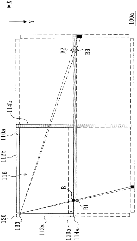
Although the area of ​​the blind area 150a of the optical touch device 100a is greatly reduced, the problem of the blind area still exists, that is, the dark spot images of B and B1 and the dark spot images of B2 and B3 will partially overlap
[0007] In view of this, the pr

Method used


Image

  • Optical touch system and positioning method thereof
  • Optical touch system and positioning method thereof
  • Optical touch system and positioning method thereof

Examples


Embodiment Construction

[0077] Figure 4 A schematic diagram showing an optical touch system according to an embodiment of the present invention. When an object 45 (such as a finger or a stylus pen) touches the touch area 48 of the optical touch system 4 , the system calculates and locates the coordinates of the object 45 . The optical touch system 4 includes a reflective element 411 , a first light guide module 421 , a second light guide module 422 , an image sensor 43 , a plurality of light detectors 49 and a processor 44 . The reflective element 411 is disposed on the first side 481 of the touch area 48, and the first light guide module 421 and the second light guide module 422 are respectively disposed on the adjacent second side 482 and the third side of the touch area 48. Side 483. The first light guide module 421 can be a combination of a light guide strip 423 and at least one light-emitting element 424, and the second light guide module 422 can also be a combination of a light guide strip 4...


PUM


Abstract

The invention provides an optical touch system and a positioning method thereof. The optical touch system is used for positioning an object in a touch area and comprises at least one reflection element, at least one light guide module, an image sensor, a plurality of first light detectors and a processor, wherein the reflection elements are arranged on a side of the touch area, the light guide modules are arranged in the touch area and on one side adjacent to or opposite to the reflection elements and are used for generating light, the image sensor is used for capturing an image of the object, the first light detectors are arranged in the touch area and on one side adjacent to the image sensor and used for detecting the object to obtain first shading information, and the processor is used for computing a coordinate of the object according to the image of the object and the first shading information.

Description

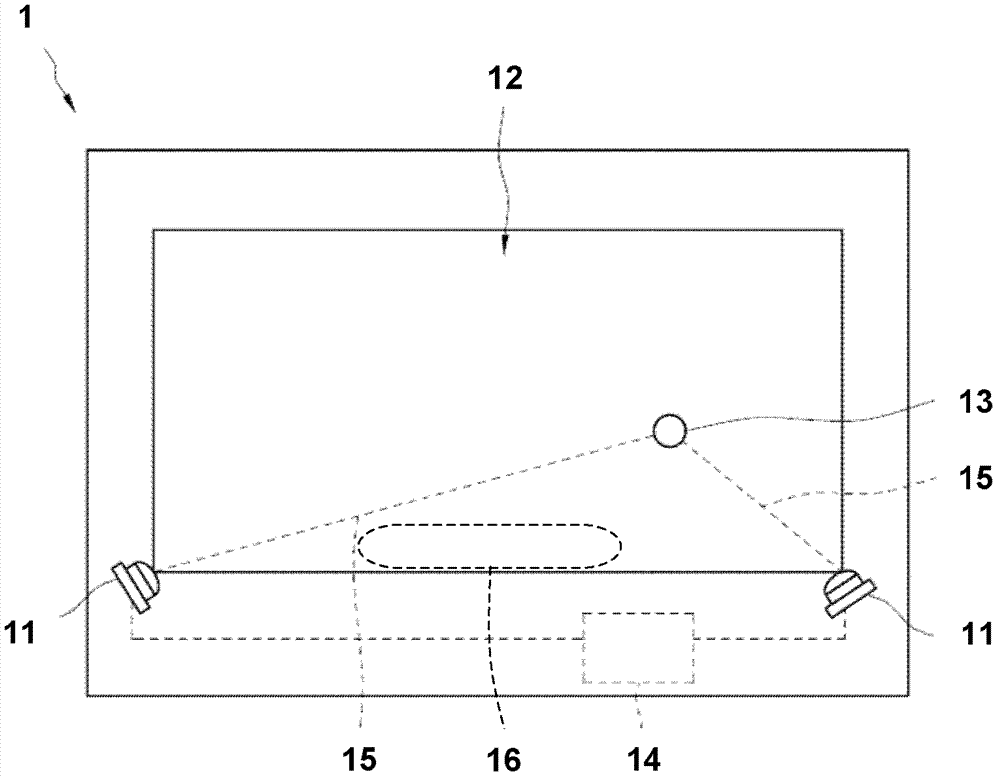
technical field [0001] The present invention relates to an optical touch system and its positioning method, in particular to an optical touch system and its positioning method which uses multiple photo-detectors to solve the blind zone problem. Background technique [0002] A touchscreen device is a device that allows users to interact with applications directly on the screen. There are various types of touch screen devices, among which the optical touch screen is a common one. [0003] figure 1 A conventional optical touch screen system 1 is shown, which is disclosed in US Pat. No. 4,782,328. Such as figure 1 As shown, the optical touch screen system 1 includes two sensors 11 for capturing images of objects 13 on the touch area 12 . The processor 14 is coupled to the two sensors 11 , and determines a sensing path 15 connecting the object 13 and the two sensors 11 by analyzing the images generated by the two sensors 11 . The processor 14 then calculates the position coo...

Claims


Application Information

Patent Timeline
IPC IPC(8): G06F3/042
Inventor 林俊生吕俊毅廖祈杰苏宗敏高铭璨
Owner PIXART IMAGING INC
Why Eureka
Try Eureka