
Local path planning method based on path point offset

A technology of local path planning and waypoints, applied in two-dimensional position/channel control, vehicle position/route/height control, non-electric variable control, etc. Adapt to changes and other problems to achieve the effect of less calculation

Active Publication Date: 2020-08-07
北京踏歌智行科技有限公司
View PDF7 Cites 3 Cited by
  • Summary
  • Abstract
  • Description
  • Claims
  • Application Information

AI Technical Summary

Problems solved by technology

At present, there are few patents and literatures on local path planning methods for self-driving mining vehicles, and it is difficult to embed existing local path planning methods into self-driving mining vehicles
Existing local path planning methods include graph search, RRT, etc., but most of these methods tend to fall into local optimal solutions, and are only suitable for environmental maps, and the calculation time is long and the efficiency is low. For example, the patent CN201611097409.5 discloses a method for A method and device for testing a route based on high-precision map planning, wherein the route planning method is based on a high-precision map, and this method has a large amount of calculation and is difficult to be widely used
Patent CN201710044287.1 discloses a local path planning method for intelligent vehicles and its device, and vehicles. The path planning method in this patent does not require map collection in advance, and the amount of calculation is small. However, the premise of the success of this path planning method is that the size of the obstacle is It is known that when the sensor detects an obstacle, the actual size of the obstacle (such as the length of the obstacle) is difficult to obtain, and the path planning method cannot adapt to the changing environment

Method used


Image

  • Local path planning method based on path point offset
  • Local path planning method based on path point offset
  • Local path planning method based on path point offset

Examples


Embodiment Construction

[0037] The present invention will be further described in detail below with reference to the accompanying drawings, so that those skilled in the art can implement the present invention in detail.

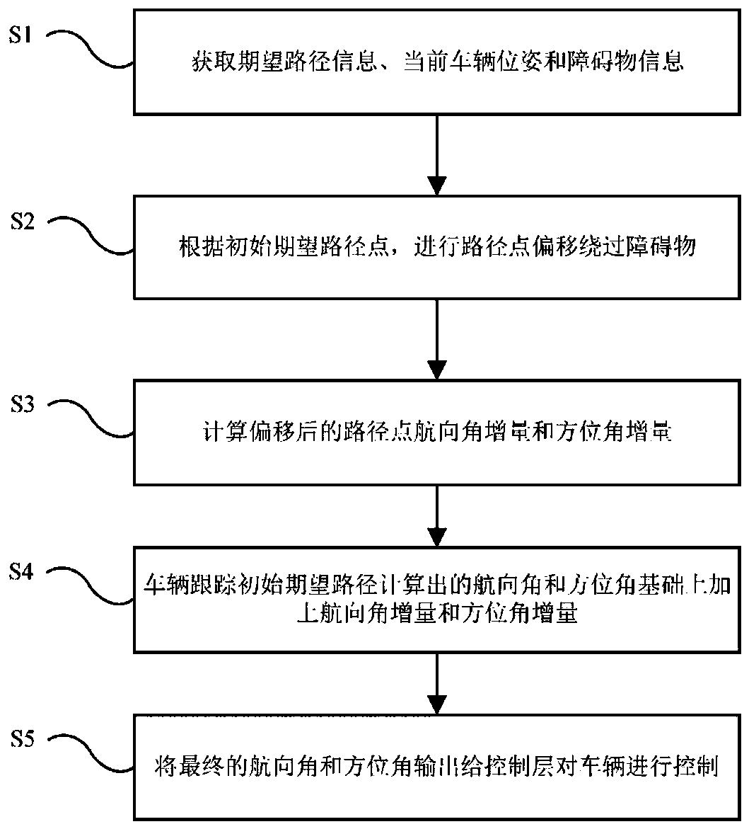
[0038] The embodiment of the present invention provides a local path planning method based on path point offset, such as figure 1 shown, including the following steps:

[0039] S1: Obtain desired path information, current vehicle pose and obstacle information;

[0040] S2: According to the information obtained in S1, perform the initial expected path point offset to bypass the obstacle;

[0041] S3: Calculate the course angle increment and azimuth angle increment of the offset path point according to the offset point of S2;

[0042] S4: The heading angle and azimuth angle calculated by the vehicle tracking the initial desired path, on this basis, add the heading angle increment and azimuth angle increment in S3;

[0043] S5: Output the heading angle and azimuth angle of S4 to the...


PUM


Abstract

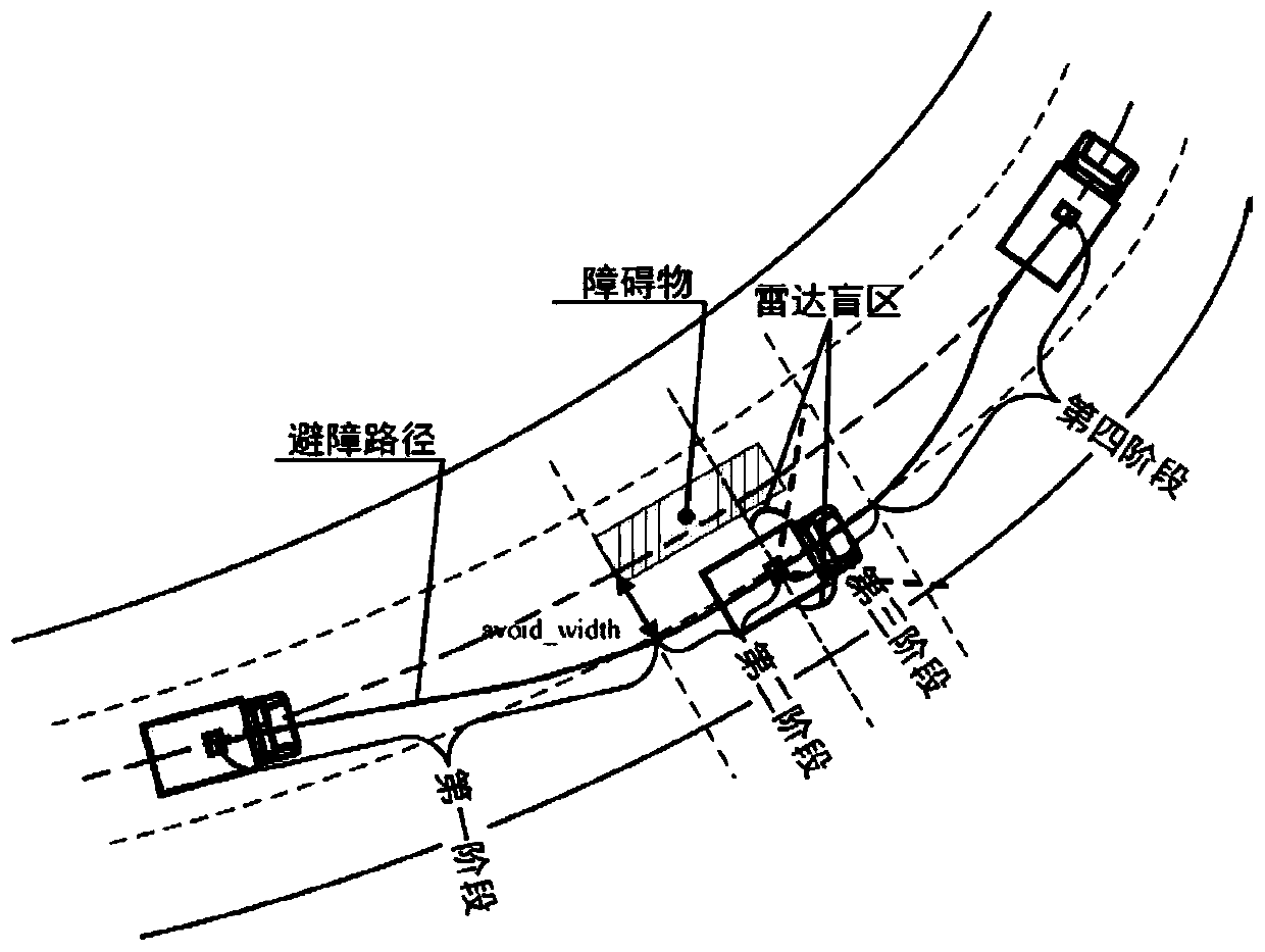
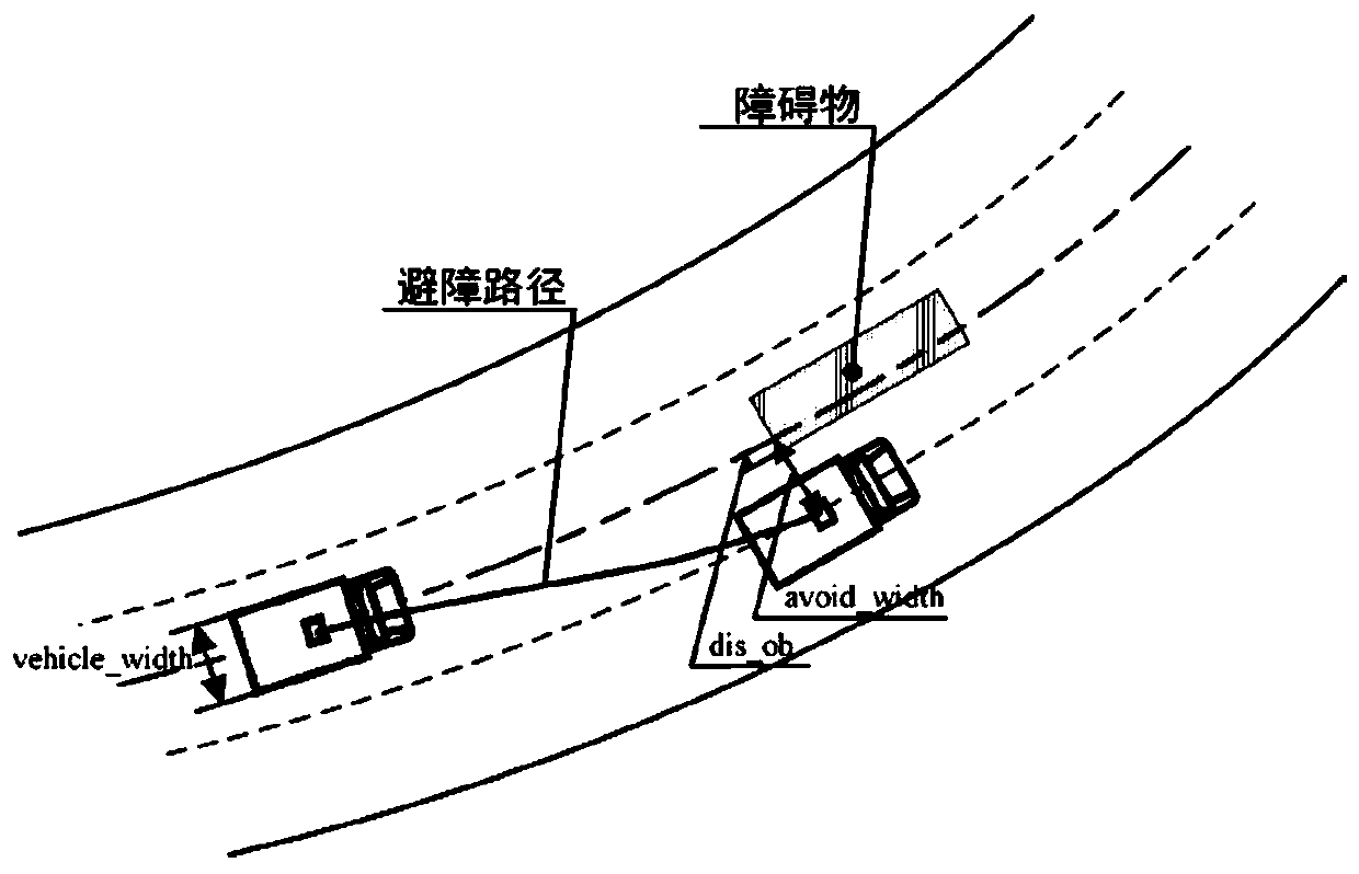
The invention discloses a local path planning method based on path point offset. The local path planning method comprises the following steps: S1, acquiring expected path information, a current vehicle pose and obstacle information; S2, according to the information obtained in the step S1, performing initial expected path point offset to bypass an obstacle; S3, calculating course angle increment and azimuth angle increment of the offset path point according to the offset point in S2; S4, the vehicle tracks the course angle and the azimuth angle calculated by the initial expected path, and thecourse angle increment and the azimuth angle increment in S3 are added on the basis; and S5, outputting the course angle and the azimuth angle of the S4 to a control layer to control the vehicle. Thepath planning method is small in calculation amount, short in research and development period and convenient for later maintenance, in the obstacle avoidance process, the transverse distance of the obstacle is detected in real time to avoid the obstacle, real-time obstacle avoidance can be performed even if the length of the obstacle cannot be obtained, and the applicability of the path planning method is improved.

Description

technical field [0001] The present invention relates to the technical field of unmanned driving, and more particularly, to a local path planning method based on path point offset. Background technique [0002] With the continuous breakthrough of autonomous driving technology, the automobile industry has achieved unprecedented development. However, in the field of autonomous driving, the technology of industrial vehicles lags behind that of civilian vehicles, and there is not a lot of research and application, such as mining vehicles and agricultural vehicles. and articulated vehicles, etc. The research on autonomous driving mining trucks will greatly reduce casualties caused by complex operating environments, and also improve the operating efficiency and comprehensive benefits of mining trucks. Partial path planning is one of the important contents of autonomous driving research. [0003] The local path planning of the autonomous driving mining vehicle is to generate a smoo...

Claims


Application Information

Patent Timeline
Patent Type & Authority Applications(China)
IPC IPC(8): G05D1/02
CPCG05D1/0257G05D1/0221G05D1/0276Y02T10/40
Inventor 刘丽冯冲黄立明
Owner 北京踏歌智行科技有限公司
Learn More