Switching method of user equipment group

A technology for user equipment and groups, applied in electrical components, wireless communication, broadcast service distribution, etc., can solve the problems of unable to switch UEs, unable to realize UE group switching, unable to trigger switching time, etc., to ensure business continuity. Effect

Active Publication Date: 2013-05-08
POTEVIO INFORMATION TECH
View PDF3 Cites 7 Cited by
  • Summary
  • Abstract
  • Description
  • Claims
  • Application Information

AI Technical Summary

Problems solved by technology

In the current S1 handover method, since the UE served by the mobile relay has not modified the serving base station, that is, the mobile relay is always serving the UE, the handover time of the UE served by the mobile relay cannot be triggered, and the mobile relay service The context of th...

Method used


Image

  • Switching method of user equipment group
  • Switching method of user equipment group

Examples


Embodiment Construction

[0019] In order to make the purpose, technical solution and advantages of the present invention clearer, the present invention will be further described in detail below in conjunction with the accompanying drawings and specific embodiments.
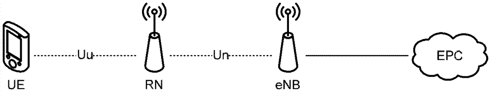
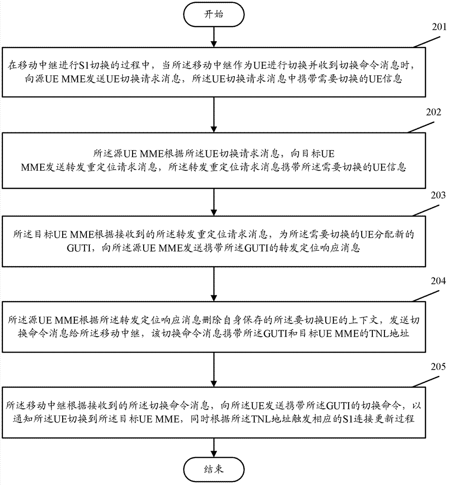
[0020] The core idea of ​​the present invention is that in the process of RN performing S1 handover, the mobile relay first performs handover as UE, and when RN receives the handover command from the serving DeNB as UE, it triggers the handover of the served UE to the target UE MME process to ensure that the context of the UE served by the RN can be transferred to the target MME, and enable the RN to establish an S1 connection with the target UE MME, so that the UE handover in the S1 handover of the mobile relay can be realized in the form of group handover, Ensuring service continuity of the UE served by the RN.

[0021] The present invention is realized based on the premise that the serving DeNB of the mobile relay transparently transmi...


PUM


Abstract

The invention provides a switching method of a user equipment group. According to the switching method of the user equipment group, users experience design (UE) which enables a mobile relay to serve is triggered so as to be switched to a target UE mobile management entity (MME) in the S1 switching process of the mobile relay and when the mobile relay is used as the UE and receives a switching order of service DeNB, so that context of the UE which is served by the mobile relay can be guaranteed to be transferred to the target MME, and S1 connection between the mobile relay and the target UE MME is established. By means of the switching method of the user equipment group, UE switching in S1 switching of the mobile relay can be achieved in a group switching mode, and the business continuity of the UE which is served by the mobile relay is ensured.

Description

technical field [0001] The invention relates to handover technology in a mobile communication system, in particular to a user equipment (UE) group handover method when a mobile relay is handed over. Background technique [0002] Currently, in the LTE-A phase, the concept of a relay (Relay) is introduced to expand the application of LTE Rel-8. Through the introduction of Relay, the requirements of extended high-speed cell coverage, group mobility, temporary network deployment, enhanced cell data service throughput, and network deployment in new areas are realized. [0003] figure 1 It is the network structure diagram after introducing the relay. Such as figure 1 shown. The relay node (Relay Node, RN) is wirelessly connected to a base station (eNB) supporting RN. This eNB is called a relay eNB (Donor eNB, DeNB). This wireless interface is a modified The E-UTRA air interface is called Un interface. [0004] The RN needs to support all functions of the eNB, which means tha...

Claims


Application Information

Patent Timeline
IPC IPC(8): H04W4/08H04W36/00
Inventor 陈喆李婷
Owner POTEVIO INFORMATION TECH
Why Eureka
Try Eureka