Pull tab turnover device and pull tab feed device

A technology of turning over device and pulling tab, applied in the field of pulling tab turning device and pulling tab supply equipment, can solve the problems such as inability to realize the forward and reverse direction or front and rear direction turning of the pulling tab, poor versatility, and laborious processing and adjustment of the transfer path.

Active Publication Date: 2013-05-15
SHANGHAI YKK ZIPPER
View PDF8 Cites 7 Cited by
  • Summary
  • Abstract
  • Description
  • Claims
  • Application Information

AI Technical Summary

Problems solved by technology

[0006] The handle transferred by the handle supply device disclosed in Patent Document 1 needs to have a specific shape. If the handle does not have a specific shape, it is impossible to reverse the front and back directions or the front and rear directions of the handle.
In addition, since the above-mentioned handle supply device uses the vibration of the transfer path to reverse the forward and reverse directions or the front and rear directions of the handle, it is necessary to directly install the front and rear reversing parts and the front and rear reversing parts on the transfer path, and cannot be used as a separate component. , therefore, poor versatility
In addition, when the front and rear reversing parts and the front and rear reversing parts are directly installed on the transfer path, it also makes the processing and adjustment of the transfer path a lot of work.

Method used


Image

  • Pull tab turnover device and pull tab feed device
  • Pull tab turnover device and pull tab feed device
  • Pull tab turnover device and pull tab feed device

Examples


example 2

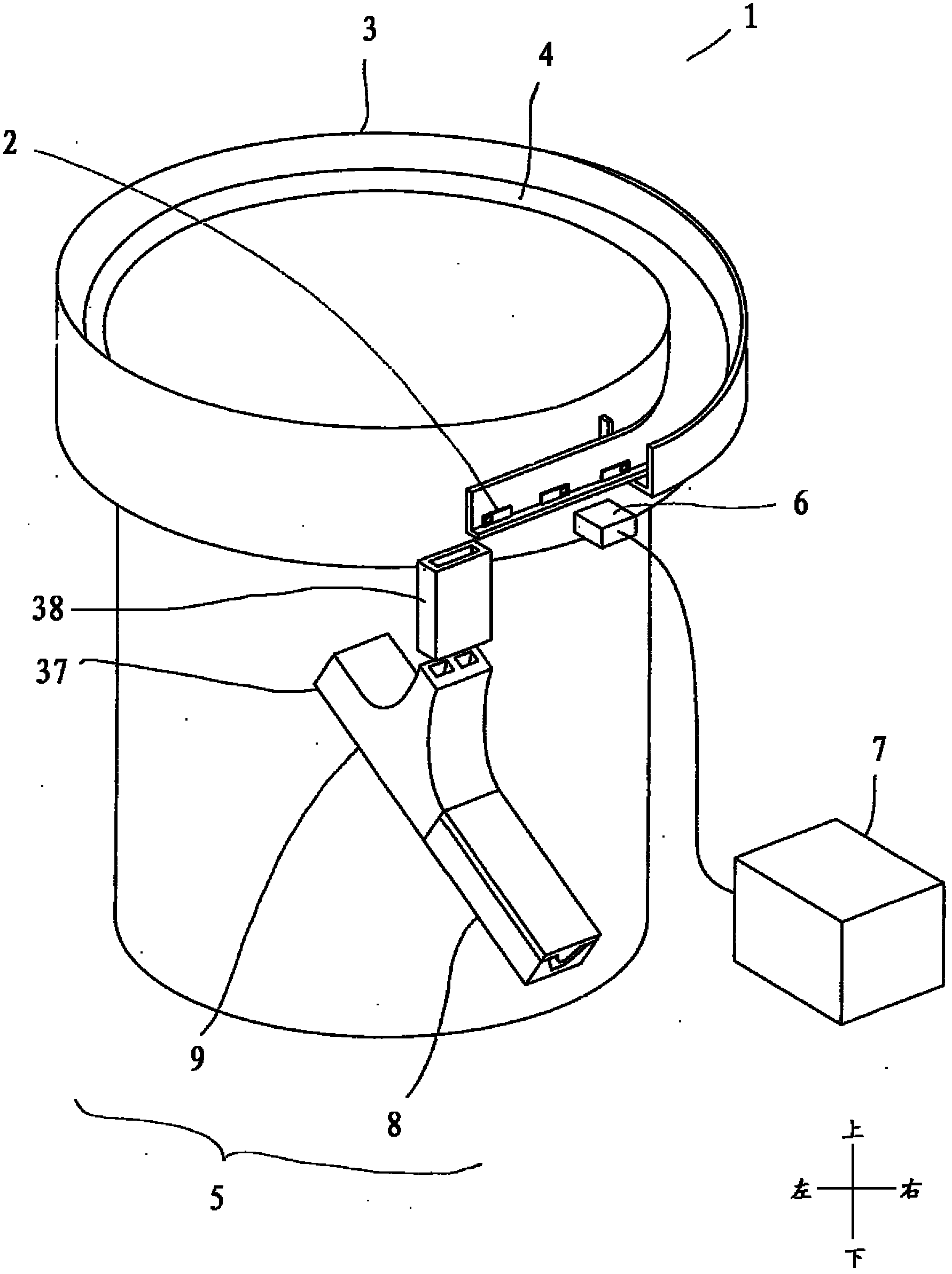
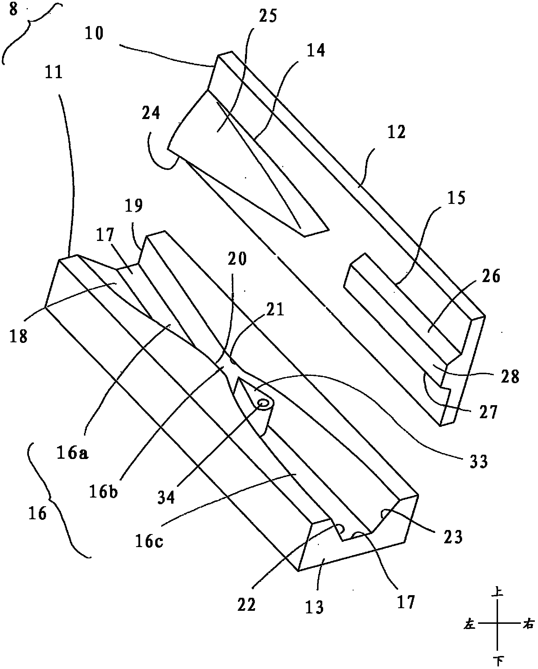
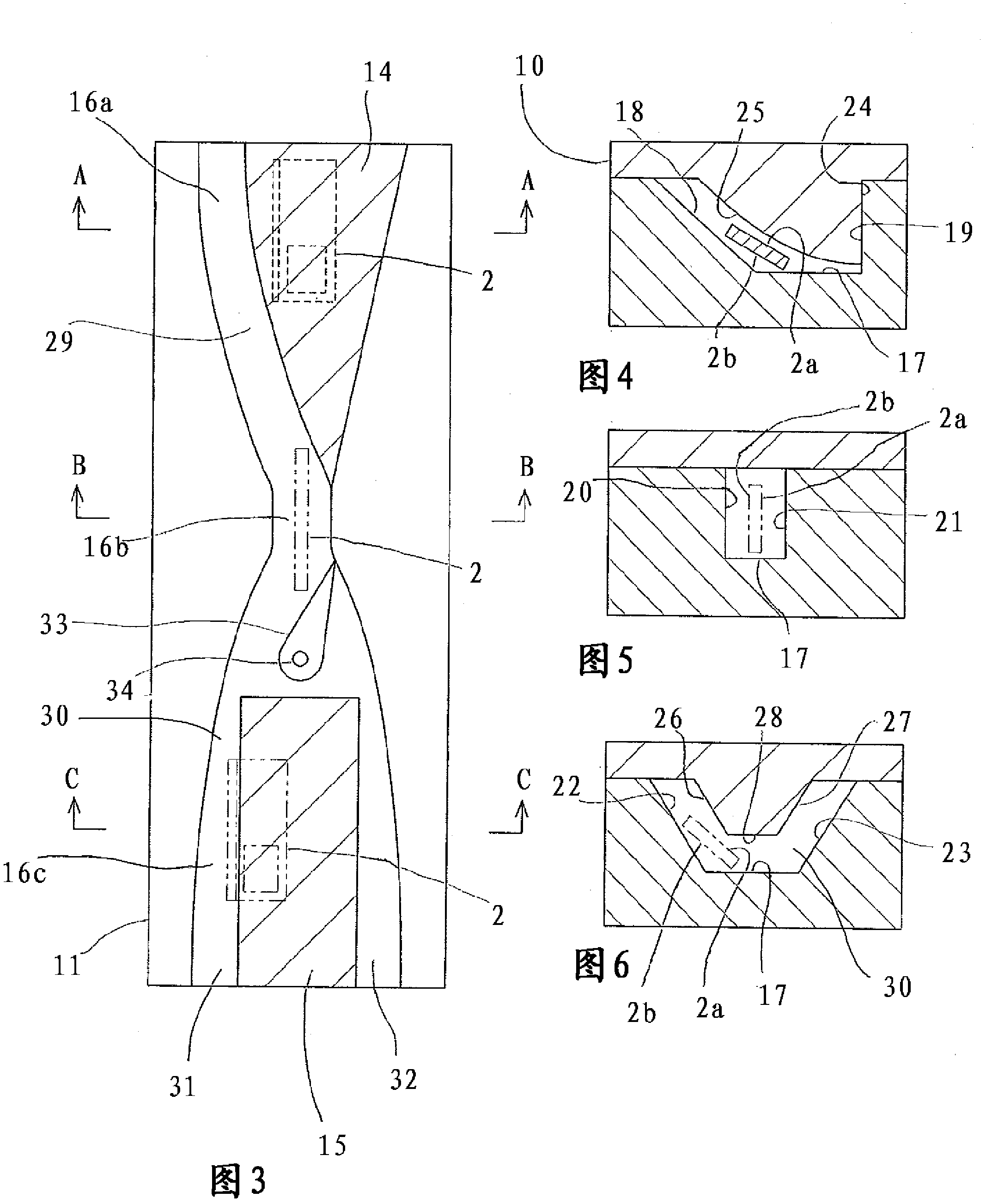
[0084] Figure 29 It is a partial enlarged view of the modification 2 of the handle supply apparatus 1. This modification 1 corresponds to the case where the front-rear inversion part 8 is not provided and only the front-rear inversion part 9 is provided. At the downstream end of the front and rear turning parts 9, the front and back turning parts 8 are not provided, but only a slideway 41 through which the pull tab 2 can directly slide down by its own gravity is provided. After the pull-tab 2 is discharged from the front and rear inverting portion 9 by gravity, it continues to be transferred downstream in the slideway 41 without reverse inverting. Of course, in this modified example, both the second component 38 and the slideway 41 can be omitted, so that the handle 2 enters the front and rear turning parts 9 directly after being discharged from the transfer path 4 .


PUM


Abstract

The invention relates to a pull tab turnover device and a pull tab feed device. The pull tab turnover device comprises an inlet, an outlet and a passage unit, wherein turnover of pull tabs is achieved through the fact that the pull tabs are enabled to pass the passage unit under the action of gravity. The pull tab feed device is provided with a storage part with the plurality of pull tabs contained, the pull tab turnover device and a conveying path, wherein the conveying path enables the pull tabs contained in the storage part to be conveyed to the pull tab turnover device. The pull tab turnover device and the pull tab feed device are high in generality and capable of being applied to the pull tabs with various design, marks and shapes. Meanwhile, cost is not increased and good convenience is brought to maintenance.

Description

technical field [0001] The invention relates to a handle reversing device and a handle supply device having the handle reversing device. Background technique [0002] In the existing handle supply equipment, during the transfer process of a plurality of handles, the front and back directions and / or the front and rear directions are often inconsistent with the predetermined direction. When the front and back directions are inconsistent with the predetermined direction, the front and back sides of the pull tab need to be turned over. [0003] Japanese Patent No. 2945255 (Patent Document 1) discloses a handle supply device having a bowl-shaped container for storing a handle and a transfer path connected to the bowl-shaped container. By simultaneously vibrating this bowl-shaped container and the transfer path, the handle can be transferred from the bowl-shaped container to the discharge end of the transfer path. And the front-back inversion part which reverses the front-back d...

Claims


Application Information

Patent Timeline
Patent Type & Authority Applications(China)
IPC IPC(8): B65G47/14
Inventor 余平朱新龙朱珏黄郭飞郁峰忻子斌
Owner SHANGHAI YKK ZIPPER
Why Eureka
Try Eureka