
High ignition rate piezoelectric lighter

A technology of ignition rate and lighter, which is applied in the direction of combustion ignition, igniter with fuel, combustion method, etc., can solve the problems of poor ignition rate of finished products, low assembly efficiency, manual thread trimming, etc., and it is easy to achieve the gap size and small deviation , The effect of improving assembly efficiency

Inactive Publication Date: 2013-05-15
余姚市民兴火机制造有限公司
View PDF0 Cites 0 Cited by
  • Summary
  • Abstract
  • Description
  • Claims
  • Application Information

AI Technical Summary

Problems solved by technology

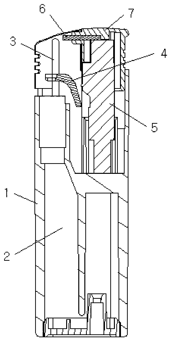
[0003] Existing piezoelectric lighters use a thin-diameter ignition wire to guide one pole of the piezoelectric body to the side of the gas nozzle. The gap size between the discharge end of the ignition wire and the gas nozzle is the key to ensure the success rate of ignition of the lighter. The ignition wire is soft and relatively long, so it is necessary to position the ignition wire correctly during the assembly process, and then rely on the workers to cut off the excess part of the ignition wire based on experience. This assembly method makes the discharge end of the ignition wire and There is a certain deviation in the size of the gap between the gas nozzles, which leads to a certain degree of poor ignition rate of the final product, and because manual trimming is required, it is not easy to realize automatic assembly, and there is a defect of low assembly efficiency

Method used


Image

  • High ignition rate piezoelectric lighter
  • High ignition rate piezoelectric lighter
  • High ignition rate piezoelectric lighter

Examples


Embodiment Construction

[0017] The embodiments of the present invention will be described in further detail below in conjunction with the accompanying drawings, but the present embodiments are not intended to limit the present invention, and any similar structures and similar changes of the present invention should be included in the protection scope of the present invention.

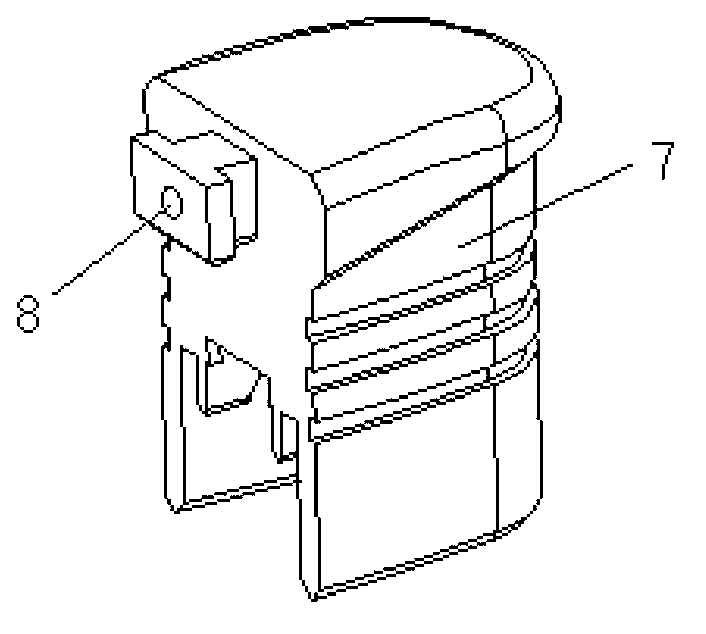
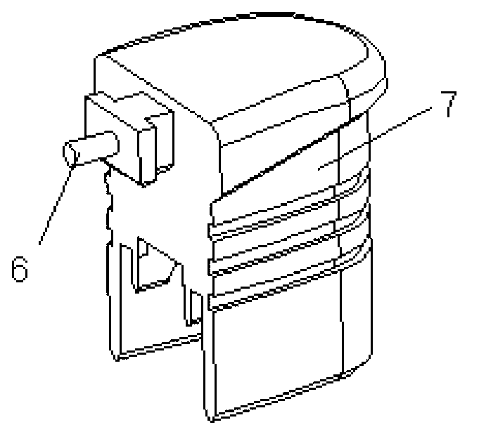
[0018] Such as Figure 1-Figure 3 As shown, a high ignition rate piezoelectric lighter provided by the embodiment of the present invention includes a lighter body 1 and a piezoelectric body 5 installed on the lighter body;

[0019] The lighter body 1 is provided with a gas cavity 2, and is provided with a gas nozzle 3 communicating with the gas cavity 2, and a rocker 4 for controlling the opening and closing of the gas nozzle 3, for pressing the rocker 4 and the piezoelectric body 5's ignition and laying of hands 7;

[0020] The gas nozzle 3 and the rocker 4 are conductors, one end of the rocker 4 is connected to the gas nozz...


PUM


Abstract

The invention discloses a high ignition rate piezoelectric lighter which is used for solving the technical problem of improving assembling efficiency and finished product ignition rate and relates to the technical field of lighters. The high ignition rate piezoelectric lighter comprises a lighter body, and piezoelectrics. The lighter body is provided with a gas cavity and an air cock communicated with the gas cavity and provided with a seesaw for controlling opening and closing of the air cock. Both the air cock and the seesaw are electric conductors. One end of the seesaw is connected with the air cock, and the other end of the seesaw is connected with an ignition press. The lower portion of the piezoelectrics is in electric connection with the air cock through the seesaw. A guide rod hole is formed in the ignition press. A hard ignition rod is fixed inside the guide rod hole. One end of the ignition rod is in electric connection with the top end of the piezoelectrics, and the other end of the ignition rod extends to the outer portion of the guide rod towards to an air outlet of the air cock and a gap is reserved between the other end of the ignition rod and the air cock. The high ignition rate piezoelectric lighter is high in ignition rate and easy to assemble.

Description

technical field [0001] The invention relates to lighter technology, in particular to a high ignition rate piezoelectric lighter technology. Background technique [0002] Such as Figure 4 As shown, the existing piezoelectric lighter mainly consists of a lighter body 21, a piezoelectric body 25, a seesaw 24, and an ignition button 27. The lighter body 21 is provided with a gas cavity 22 and a gas nozzle 23. The rocker 24 is used to control the opening and closing of the gas nozzle 23. One pole of the piezoelectric body 25 is electrically connected to the gas nozzle 23 through the rocker 24, and the other pole is ignited. The wire 26 leads to the gas nozzle 23 sides. When igniting, the ignition button presses down the seesaw to open the gas nozzle, and presses the piezoelectric body to generate piezoelectric effect. The electric load generated by the piezoelectric body generates electric sparks between the ignition wire and the gas nozzle, thereby turning the gas The gas fro...

Claims


Application Information

Patent Timeline
IPC IPC(8): F23Q2/34
Inventor 邵剑辉
Owner 余姚市民兴火机制造有限公司
Learn More