
High temperature test chamber

A high-temperature test chamber and heat-resistant technology, applied in the direction of measuring devices, instruments, scientific instruments, etc., can solve the problems of slow temperature rise, difficulty in reaching the temperature, increasing the volume of test equipment, etc., and achieve the effect of reducing costs

Inactive Publication Date: 2013-05-15
范福仓
View PDF0 Cites 1 Cited by
  • Summary
  • Abstract
  • Description
  • Claims
  • Application Information

AI Technical Summary

Problems solved by technology

[0003] In order to overcome the existing situation, the existing high-temperature test equipment mostly uses electric heating wire as the heating element. Using this method not only increases the volume of the test equipment, but also slows down the temperature rise, and it is not easy to reach the required temperature, which increases the cost of the test. Insufficient, the present invention provides a kind of high-temperature test box, and it heats up fast, reaches the required temperature easily, also reduces the cost of test

Method used


Image

  • High temperature test chamber
  • High temperature test chamber
  • High temperature test chamber

Examples


Embodiment Construction

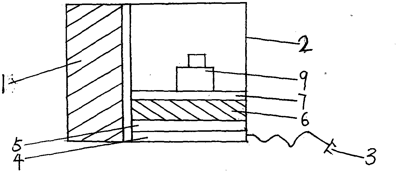
[0013] exist figure 1 Among them, the door (1) is next to the test box shell (2), and the power plug (3) is located below. There is a heat-resistant protective net (7) inside the test box shell (2), and the heat-resistant protective net (7) The test article (9) is placed above, the electrode (6) is below the heat-resistant protective net (7), the fan (5) is below the electrode (6), and the circuit board (4) is below the fan (5).

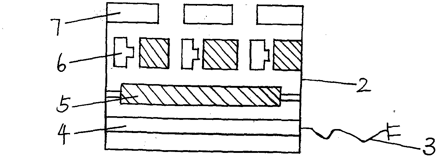
[0014] exist figure 2 Among them, the top of the test box shell (2) is a heat-resistant protective net (7), the electrode (6) is located below the heat-resistant protective net (7), the fan (5) is located below the electrode (6), and the fan (5) Below is the circuit board (4) and the power plug (3). When the power is turned on, an arc is generated on the electrode (6), and the arc generates high temperature. At the same time, the fan (5) below the electrode (6) also starts to rotate, and the fan ( 5) Blow the high temperature generated by the arc ...


PUM


Abstract

The invention discloses a high temperature test chamber. A heat-resisting protective net is arranged in a shell of the high temperature test chamber, a test object is placed on the heat-resisting protective net, an electrode is arranged under the heat-resisting protective net, a fan is arranged under the electrode, and a circuit board and a power plug are arranged under the fan. When a power supply is switched on, the electrode generates electric arcs, the electric arcs generate a high temperature, meanwhile, the fan under the electrode also starts to rotate, the fan blows the high temperature generated by the electric arcs towards the heat-resisting protective net and the test object placed on the heat-resisting protective net, and the temperature in the chamber rises quickly within short time, so that the temperature required in the test can be realized easily, and the test cost is lowered.

Description

Technical field [0001] The invention relates to a device for testing and detecting high-temperature materials. Background technique [0002] At present, the existing high-temperature test equipment mostly uses electric heating wire as the heating element. Using this method not only increases the volume of the test equipment, but also slows down the temperature rise, which makes it difficult to reach the required temperature and increases the test cost. Contents of the invention [0003] In order to overcome the existing situation, the existing high-temperature test equipment mostly uses electric heating wire as the heating element. Using this method not only increases the volume of the test equipment, but also slows down the temperature rise, and it is not easy to reach the required temperature, which increases the cost of the test. Insufficient, the present invention provides a kind of high-temperature test chamber, and it heats up fast, reaches required temperature easil...

Claims


Application Information

Patent Timeline
IPC IPC(8): G01N33/00
Inventor 范福仓
Owner 范福仓
Learn More