
an electronic device

A technology for electronic devices and fans, applied in the direction of cooling/ventilation/heating renovation, etc., can solve the problems of high cost, difficult system space configuration, complex structure of two sheet metal walls, etc.

Active Publication Date: 2015-10-21
INVENTEC PUDONG TECH CORPOARTION +1
View PDF6 Cites 0 Cited by
  • Summary
  • Abstract
  • Description
  • Claims
  • Application Information

AI Technical Summary

Problems solved by technology

[0004] The purpose of the present invention is to provide an electronic device, so as to improve the problem of difficult system space configuration caused by two sheet metal walls, the difficulty of disassembly and assembly due to the complicated structure of the two sheet metal walls, and the problem of disassembling the two sheet metal walls. Problems with higher cost due to sheet metal walls and more snap rings

Method used


Image

  • an electronic device
  • an electronic device
  • an electronic device

Examples


Embodiment Construction

[0035] The following will clearly illustrate the spirit of the present invention with the accompanying drawings and detailed descriptions. After understanding the preferred embodiments of the present invention, any person of ordinary skill in the art can make changes and modifications based on the technology disclosed in the present invention, and without departing from the spirit and scope of the present invention.

[0036] The accompanying drawings are for illustration purposes only and are not drawn to original scale. On the other hand, well-known components and steps have not been described in the embodiments in order not to limit the invention unnecessarily.

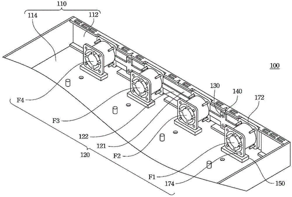
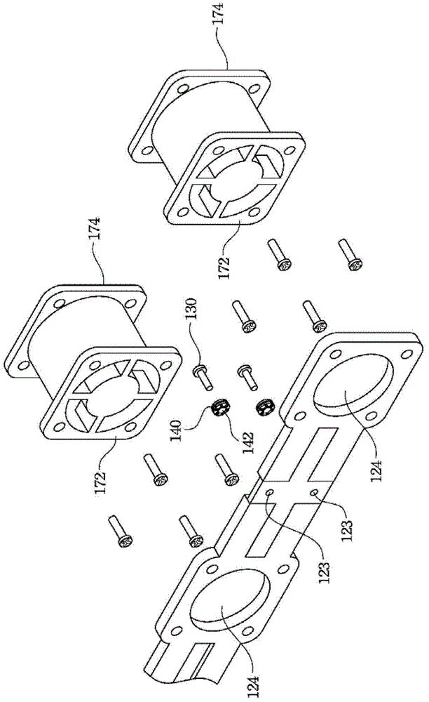
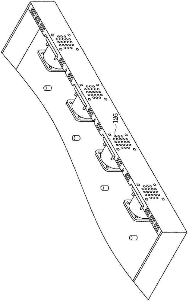
[0037] figure 1 It is a specific schematic diagram of an electronic device 100 according to an embodiment of the present invention. The electronic device 100 includes a casing 110 and a fan unit assembly 120 . The casing 110 has a front panel 112 and a bottom panel 114 , and the front panel 112 and the bottom pan...


PUM


Abstract

The invention provides an electronic device. The electronic device comprises a shell body and a fan unit assembly. The shell is provided with a front panel and a base plate, wherein the front panel and the base plate are perpendicular to each other. The fan unit assembly comprises a plurality of fan units and a plate body. Each fan unit is provided with a first end face. The first end face of each fan unit is fixed on the plate body through a fastener. The plate body is arranged at the inner side of the front panel in parallel, wherein the plate body is arranged between the fan units and the front panel and gaps exist between the bottom surfaces of the fan units and the base plate. The electronic device can solve the problems that space arrangement of a system is hard due to a complex structure of two metal plate walls, disassembly and assembly are different because of complicated structures of the two metal plate walls, and cost is high caused by assembly of the two metal plates and more buckle rings.

Description

technical field [0001] The invention relates to a shock absorber, in particular to a fan shock absorber. Background technique [0002] For the system fan shock absorber, the general method is to use a box or two sheet metal walls, and the fan can be hung on the corresponding position of the sheet metal wall after installing the fan fixing device (Fan-mount) to achieve fan avoidance. Shock effect. When there are higher requirements for shock absorption, the buckle (Grommet) can be used. [0003] However, in today's trend of thinner and smaller systems, the use of two sheet metal walls will cause the problem of difficult system space configuration, and the structure of the two sheet metal walls is more complicated, making disassembly and assembly more difficult. In addition, the general system needs to configure two sheet metal walls and more buckles, which also has the problem of high cost. Contents of the invention [0004] The purpose of the present invention is to pro...

Claims


Application Information

Patent Timeline
Patent Type & Authority Patents(China)
IPC IPC(8): H05K7/20
Inventor 宋二振王世锋
Owner INVENTEC PUDONG TECH CORPOARTION
Learn More