Spring positioning device and spring positioning method

A spring positioning and fixing device technology, applied in metal processing equipment and other directions, can solve the problems of time-consuming and laborious, reduce the production efficiency of spring mattresses, etc., and achieve the effect of high production efficiency

Active Publication Date: 2013-05-22
宁波望春宏枫智能装备有限公司
View PDF9 Cites 2 Cited by
  • Summary
  • Abstract
  • Description
  • Claims
  • Application Information

AI Technical Summary

Problems solved by technology

In the past, it was manually arranged to ensure that the nodes of each spring would not be located on the line through which the

Method used


Image

  • Spring positioning device and spring positioning method
  • Spring positioning device and spring positioning method
  • Spring positioning device and spring positioning method

Examples


Example Embodiment

[0017] The present invention will be further described in detail below with reference to the drawings and specific embodiments: In this embodiment, the side of the plate 104 facing the spring 2 is defined as the front of the plate, and the side of the plate 104 facing away from the spring 2 is defined as the back.
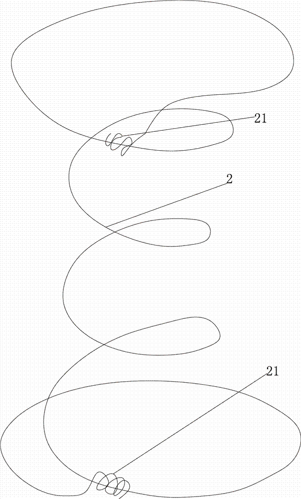
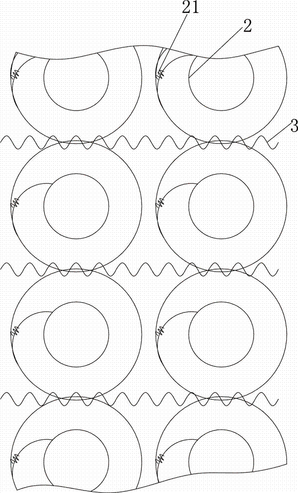
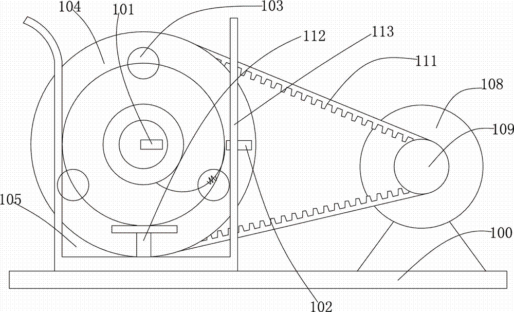
[0018] See image 3 with Figure 4 , The spring positioning device includes a base 100. A base 106 and a motor 108 are fixed on the base 100. One end of a rod 107 is fixed on the base 106. A circular plate 104 is rotatably connected to the other end of the rod 107. The plate 104 The center of the circle is located on the axis of the rod 107, a transmitter 101 is fixed on the end surface of the rod 107, and the main part of the transmitter 101 is a luminous tube. Three electromagnets 103 are fixed on the plate 104, and the electromagnet 103 and the plate 104 together form a fixing device for the spring 2. The working principle is to use the attractive force when the el...


PUM


Abstract

A spring positioning device comprises an emitter, a receiver, a fixing device used for fixing a spring, and a driving mechanism used for driving the fixing device to rotate, wherein the spring is fixed on the fixing device, and when the fixing device rotates, only a node of the spring passes through the connecting line between the emitter and the receiver. According to the spring positioning device and a spring positioning method, positioning of angles of the spring can be automatically achieved, the direction of the spring node conveyed to a perforating machine is enabled not to be located on a route which a steel wire passes through, production efficiency is high, and positions of the spring can be adjusted automatically as required.

Description

technical field [0001] The invention relates to the technical field of spring mattress processing equipment, in particular to a spring positioning device and positioning method. Background technique [0002] figure 1 Shown is a spring 2 for a box spring mattress, the diameter of the ends of the spring 2 is larger than the diameter of the middle part, and the ends of the spring 2 each have a node 21 . The springs used in mattresses are all standardized by machines, and the joints of each spring are from the same position. These springs need to be connected into one body through a net threading machine to form a spring bed net, and the spring bed net is outsourced with cloth to form a spring mattress. see figure 2 , these springs 2 need to be connected in series through the mesh threading machine. When threading the mesh, the mesh threading machine needs to avoid the nodes 21 as much as possible, otherwise the steel wire threading the mesh will encounter obstacles. [000...

Claims


Application Information

Patent Timeline
IPC IPC(8): B21F33/04
Inventor 苏卓洪刘锋
Owner 宁波望春宏枫智能装备有限公司
Why Eureka
Try Eureka