
Turnover frame

A technology of flipping frame and rotating frame is applied in the field of flipping frame, which can solve the problems of increased production cost, low reliability, easy deformation of the panel, etc., and achieves the effect of reducing production cost, high reliability and not easy to deform.

Inactive Publication Date: 2013-05-22
江苏中南模板科技有限公司
View PDF5 Cites 10 Cited by
  • Summary
  • Abstract
  • Description
  • Claims
  • Application Information

AI Technical Summary

Problems solved by technology

[0002] The clamping device in the current overturning rack is usually clamped by oil cylinders at both ends, controlled by a control circuit. This circuit control has low reliability, and the panel is easily deformed during the overturning process. It is composed of two oil cylinders at the same time, which increases the production cost. , at the same time, the control is inconvenient, and the formwork is prone to slide when it is turned up. Therefore, in order to solve the above problems, a new technical solution is provided to meet the needs

Method used


Image

  • Turnover frame
  • Turnover frame
  • Turnover frame

Examples


Embodiment Construction

[0017] In order to deepen the understanding of the present invention, the present invention will be further described below in conjunction with the embodiments and accompanying drawings. The embodiments are only used to explain the present invention and do not constitute a limitation to the protection scope of the present invention.

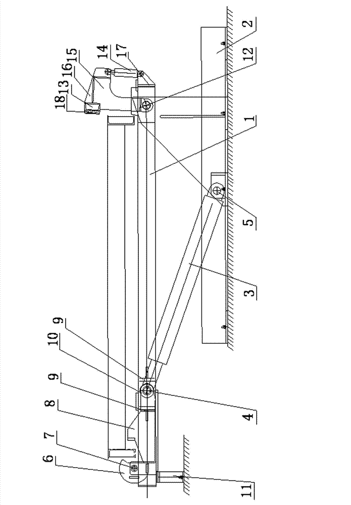
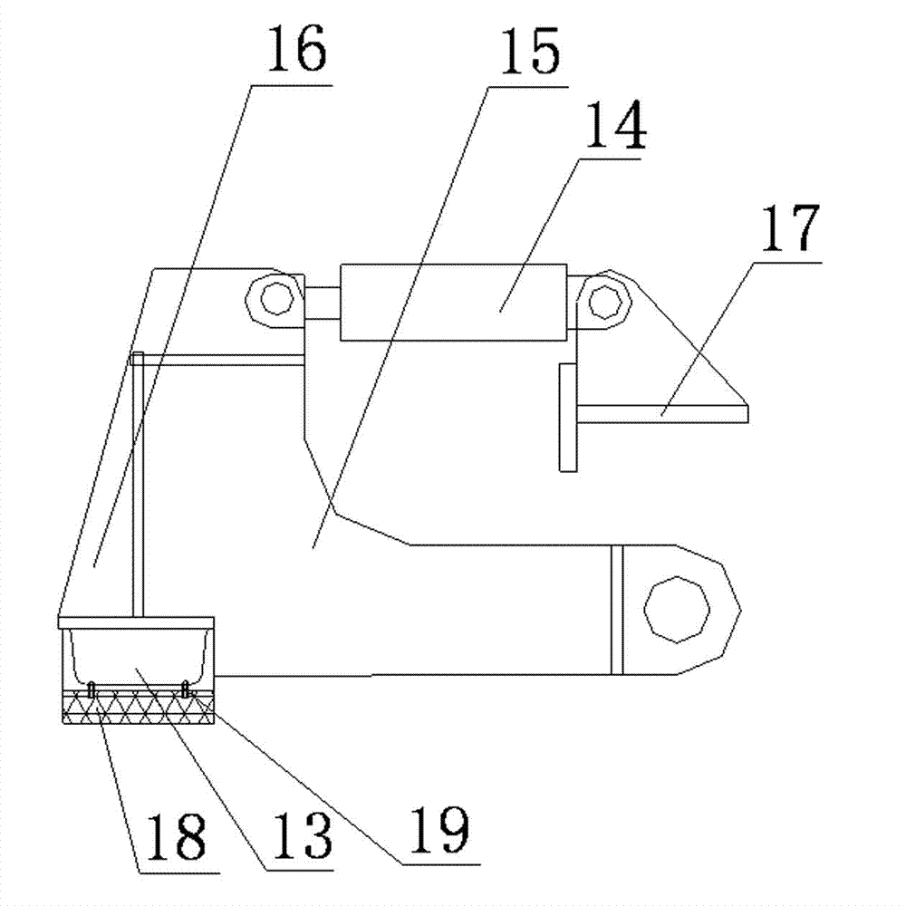
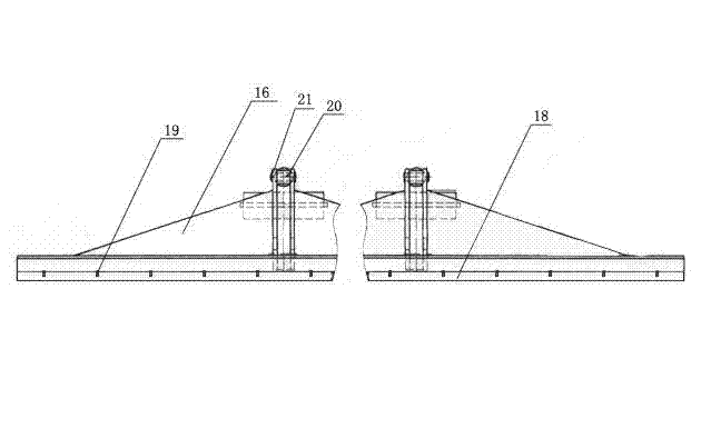
[0018] Such as Figure 1-3 As shown, the reversing frame of the present invention includes a rotating frame 1, a clamping device, a pushing device and an underframe 2, the underframe 2 is movably connected with the rotating frame 1 through an overturning oil cylinder 3, and the top of the overturning oil cylinder 3 is connected to the rotating frame through an upper shaft 4. The frame 1 is movably connected, the bottom end of the turning cylinder 3 is movably connected with the bottom frame 2 through the lower shaft 5, and a clamping device is provided between the top of the rotating frame 1 and the upper shaft 4, and the clamping device includes ...


PUM


Abstract

The invention discloses a turnover frame. The turnover frame is characterized by comprising a rotary frame, a clamping device, a push-and-block device, and a bottom frame. The bottom frame is movably connected with the rotary frame through a turnover oil cylinder, the top end of turnover oil cylinder is movably connected with the rotary frame through an upper shaft, the bottom end of the turnover oil cylinder is movably connected with the bottom frame through a lower shaft, the clamping device is arranged between the top end of the rotary frame and the upper shaft, the push-and-block device is arranged at the tail end of the rotary frame, and the rotary frame and the push-and-block device are movably connected through a rotary shaft. The turnover frame has the advantages that the turnover frame is used for rotating a framework through a mechanical method, manufacture cost is largely lowered due to the fact that a mechanical and automatic pushing, clamping and self-dragging method is adopted, and at the same time, the mechanical method is high in reliability compared with a circuit control method a panel is not easy to deform, and the push-and-block device of a preformed piece edge mould is added on the rotary frame, and therefore when the framework is turned over, a preformed piece cannot slide down.

Description

technical field [0001] The invention relates to an overturning frame, which belongs to the field of construction equipment. Background technique [0002] The clamping device in the current overturning rack is usually clamped by oil cylinders at both ends, controlled by a control circuit. This circuit control has low reliability, and the panel is easily deformed during the overturning process. It is composed of two oil cylinders at the same time, which increases the production cost. At the same time, the control is inconvenient, and the formwork is prone to slide when it is turned up. Therefore, in order to solve the above problems, a new technical solution is provided to meet the needs. Contents of the invention [0003] The object of the present invention is to provide an overturning frame. [0004] The technical scheme adopted in the present invention is: [0005] The turning frame includes a rotating frame, a clamping device, a pushing device and a bottom frame, the b...

Claims


Application Information

Patent Timeline
Patent Type & Authority Applications(China)
IPC IPC(8): B28B17/00
Inventor 黄建国
Owner 江苏中南模板科技有限公司
Learn More