Underwater construction method of steel tube

A construction method and technology for steel pipes, which are applied in pipeline laying and maintenance, pipes/pipe joints/fittings, machinery and equipment, etc., can solve the problems of underwater construction of steel pipes, long construction period and high risks, and save water transportation costs and construction costs. The effect of low cost and high construction quality

Inactive Publication Date: 2010-04-07
珠海澳新起重科技有限公司
View PDF0 Cites 7 Cited by
  • Summary
  • Abstract
  • Description
  • Claims
  • Application Information

AI Technical Summary

Problems solved by technology

Difficult construction, long construction period, high risk and high cost have always plagued the underwater construction of steel pipes

Method used


Image

  • Underwater construction method of steel tube
  • Underwater construction method of steel tube
  • Underwater construction method of steel tube

Examples


Embodiment 1

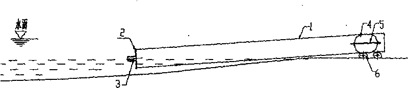
[0036] Example 1, such as figure 1 As shown, the construction method of the sewage pipe in water. Steel pipe 1 diameter is 2m, and total length is 1000m, and original design is that steel pipe 1 is divided into 20 joints, now changes construction by technical scheme of the present invention, method is as follows:

[0037] 1. The front end of the first steel pipe 1 is blocked with a blind plate 2, and the diameter of the inlet and outlet 3 is 200 mm on the blind plate 2, and a remote control valve is installed;

[0038] 2. Let the front section of the first steel pipe 1 enter the water, and the rear section is assembled and welded with other steel pipes on the shore;

[0039] 3. When launching into the water, block the mouth of the steel pipe 1 on the shore with an oval-shaped sealing air bag 4. The total length of the air bag 4 is 3m, its nominal diameter is 2m, and its aspect ratio is 1.5. , the perimeter of the airbag 4 is 5m, which is 80% of the inner perimeter of the ste...

Embodiment 2

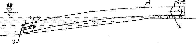
[0046] Example 2, such as image 3 As shown, the water intake steel pipe water construction method. The diameter of the steel pipe is 2.5m, and the total length is 4000m. The construction steps of the technical solution of the present invention are as follows:

[0047] 1. The front end of the first section of steel pipe 1 is blocked with a plugging air bag 4. The plugging air bag 4 has a piercing tube 5 with a diameter of 375mm. The inlet and outlet 3 on the piercing tube 5 are installed with remote Control the valve, if there is no emergency, the blocking air bag 4 at the front end generally cannot be exhausted;

[0048] 2. Let the front section of the first steel pipe 1 enter the water, and the rear section is assembled and welded with other steel pipes on the shore;

[0049] 3. When launching into the water, block the mouth of the steel pipe 1 on the shore with a sealing air bag 4;

[0050] The total length of the airbag 4 is 7.5m, with hemispherical heads at both ends, ...


PUM

PropertyMeasurementUnit
Diameteraaaaaaaaaa
Total lengthaaaaaaaaaa
Diameteraaaaaaaaaa

Abstract

The invention is an underwater construction method of a steel tube, belonging to the technical field of underwater engineering and comprising the following steps: plugging steel tube openings at a front end and an on-shore segment of the first section of the steel tube by an air bag or a blind plate; enabling the steel tube to float on the water surface by inflating the steel tube, thus facilitating the steel tube to be fed into water; filling water in the steel tube to lead the steel tube to sink underwater, thus realizing continuous welding construction of the steel tube; changing underwater work to on-shore work, thus omitting water transportation of the steel tube; and welding and launching the steel tube section by section, thus needing no underwater work of divers and cooperation of a lot of large-scale ship engine equipment such as floating cranes, barges, tugboats and the like. The method in the invention is suitable for various water area constructions; the entire steel tube is integrated into a whole, and the construction quality is far higher than that in the prior art; and the construction risk and the construction cost are lower.

Description

technical field [0001] The invention relates to an underwater construction method of a steel pipe, which belongs to the technical field of underwater engineering. Background technique [0002] In the underwater construction of steel pipes, the transportation and installation of steel pipes are often involved. The steel pipe needs to be divided into many sections, and the underwater flange connection or Harvard connection requires the cooperation of many large marine equipment such as floating cranes, barges and tugboats. If construction is carried out in a shallow water area, these marine machinery and equipment cannot be put into use. [0003] The steel pipes are connected underwater, requiring divers to work underwater, which is greatly affected by terrain, currents and climate, and it is even more difficult to work in waters with rapid currents and large surges. Once the connection fails, it is necessary to build a cofferdam at the joint of the steel pipe, and take reme...

Claims


Application Information

Patent Timeline
IPC IPC(8): F16L1/26
Inventor 钟爱民
Owner 珠海澳新起重科技有限公司
Why Eureka
Try Eureka